Table of Contents
Mixed-Port for ROS: Accessing ROS nodes from software components
This tutorial describes how to model a Mixed-Port Component for ROS in order to access ROS nodes from software components in the SmartMDSD Toolchain.
Basic Information
| Level | Experienced |
|---|---|
| Role | Component Supplier |
| Assumptions | You know how to model software components in general and how to implement business logic in general (see Develop Your First Software Component). You have a basic understanding of ROS. |
| System Requirements | - ROS Kinetic installation - a ROS Linux Joystick package - the SmartMDSD Toolchain v3.8 (or newer) - A Linux compatible joystick device (e.g. a Logitech Dual Action joystick) |
| You will learn | - How to model a mixed-port software component with a ROS Port - How to implement the business logic using the generated ROS infrastructure |
Video tutorial
There is a video tutorial howing how to develop and use mixed-port components: https://www.youtube.com/watch?v=N1oMMIBIx5k
Introduction
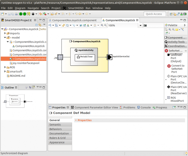
In this tutorial you will learn how to add a plain ROS port to a software component. As an example, this tutoral will use the ComponentRosJoystick that is specified as shown in the following screenshot:
To create this component, please follow the instructions given in Develop Your First Software Component. Make sure you are creating a reference to the CommBasicObjects domain model project that holds the service definition for JoystickService.
For this component we will add a plain ROS port (i.e. a topic subscriber) that interacts with a ROS node that generates joystick command updates. The ComponentRosJoystick will read these joystick updates regularly with an update frequency of 10 Hz, translate each value into a CommJoystick communication object, and finally push the transformed object to the JoystickServiceOut output service of the ComponentRosJoystick. In this way, the ComponentRosJoystick acts as a bridge between the ROS and the SmartMDSD worlds. More precisely, the ComponentRosJoystick uses the joystick driver abstraction implemented in ROS and provides an abstracted service that can be used by all systems realized with the SmartMDSD Toolchain.
Add a plain ROS port
For activating the ROS feature and for modeling the ROS MixedPort, a new model with the file extension .rosinterfacespool needs to be created within a component project. For our example, we will create the model file named joy.rosinterfacespool. This model file consists of an abstract representation of the available ROS interfaces that can be used in our component (we will select a subset of these interfaces for our component model). This model can be shared between several components.
The content of the joy.rosinterfacespool for our example looks as follows:
As can be seen, this model specifies two ROS (topic) subscriber interfaces, one named _diagnostics and the other named _joy. We therefore select it as a port of our mixed-port component. For our example, we are interested in the _joy subscriber interface (that we will select in the followup model). Moreover, the model specifies a topicName that is the ROS topic address the subscriber will connect to, and the type which specifies the related ROS message type. Both informations are used by the SmartMDSD ROS generator to generate C++ code that integrates the ROS infrastructure with the component's internal infrastructure.
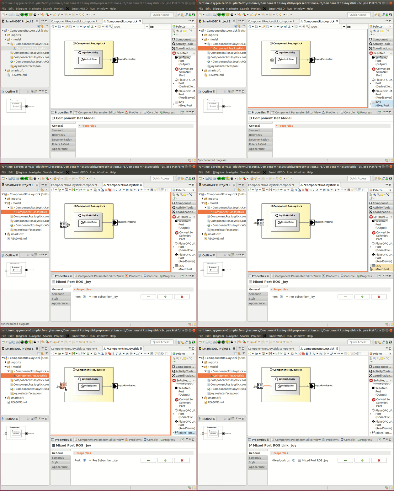
The ROS port can be selected in the component graphical model as follows:
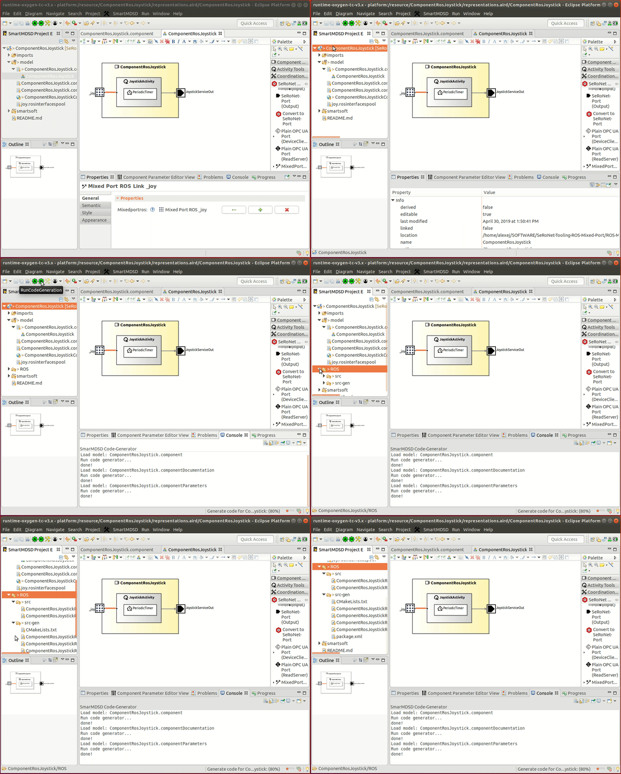
After saving the model, we can trigger the ROS C++ code generation as follows:
The generated ROS C++ code can be found in a new subfolder named ROS within the component project (see on the left of the above screenshot). Here you can see that several helper classes are generated that implement the initialization of the ROS infrastructure (such as the calling of the methods ros::init(…), ros::spin(), and ros::shutdown), as well as the instantiation of the selected ROS subscriber, in our case the ros::Subscriber named _joy.
Moreover, a CMakeLists.txt file is generated that uses the ROS catkin build infrastructure for compiling the ROS related code parts. Please note, that the generated cmake file deviates from the typical ROS cmake files in the sense that the actual creation of the executable is deactivated and is performed instead by the component's top-level cmake file (which simply includes the ROS cmake file).
Implement the user logic of the ComponentRosJoystick
In this section, we will use the generated ROS C++ infrastructure (see preceding section) to provide additional user logic for our ComponentRosJoystick component. This user code mostly is about transforming an incoming ROS joystick message update into a CommJoystick communication object, and pushing this object to the JoystickServiceOut output port.
Therefore we will refine the initially generated implementation of two classes:
- ComponentRosJoystickRosPortCallbacks: this class can be found in the subfolder: ROS/src
- JoystickActivity: this class can be found in the subfolder: smartsoft/src
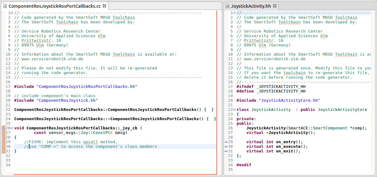
The ComponentRosJoystickRosPortCallbacks class implements the callback functions for all selected ROS subscribers, which in our case results to the single callback method named _joy_cb(…) (see on the left of the above screenshot). As the FIXME comment in the imlementation suggests, this generated method is just a skeleton with an empty implementaiton. For our example we will propagate the incoming sensor_msgs::Joy message to the JoystickActivity class so it can be processed there.
As for the JoystickActivity class (see on the right of the above screenshot), we will extend the generated skeleton by an update method (which will be called from the _joy_cb(…) callback method. Moreover we will implement the on_execute() method such that it transforms the incoming sensor_msgs::Joy into a CommJoystick object, and pushes the result to the JoystickServiceOut output port. The example implementation of the three related C++ files is provided for download in the following.
- ComponentRosJoystickRosPortCallbacks.cc
#include "ComponentRosJoystickRosPortCallbacks.hh"

// include component's main class
#include "ComponentRosJoystick.hh"

ComponentRosJoystickRosPortCallbacks::ComponentRosJoystickRosPortCallbacks() {  }

ComponentRosJoystickRosPortCallbacks::~ComponentRosJoystickRosPortCallbacks() {  }

void ComponentRosJoystickRosPortCallbacks::_joy_cb (const sensor_msgs::Joy::ConstPtr &msg)
{
	COMP->joystickActivity->update_joystrick_msg(msg);
}
Here in the generated _joy_cb(…) we simply delegate the handling of this upcall to the method update_joystrick_msg(msg) that is implemented in the JoystickActivity (see below).
- JoystickActivity.hh
#ifndef _JOYSTICKACTIVITY_HH
#define _JOYSTICKACTIVITY_HH

#include "JoystickActivityCore.hh"

#include <mutex>
#include <sensor_msgs/Joy.h>

class JoystickActivity  : public JoystickActivityCore
{
private:
	std::mutex mtx;
	CommBasicObjects::CommJoystick comm_joy;
public:
	JoystickActivity(SmartACE::SmartComponent *comp);
	virtual ~JoystickActivity();

	void update_joystrick_msg(const sensor_msgs::Joy::ConstPtr &msg);

	virtual int on_entry();
	virtual int on_execute();
	virtual int on_exit();
};

#endif
In the header of the JoystickActivity class we add the new method update_joystrick_msg(…) and add a local member CommJoystick comm_joy which will be updated each time the update_joystrick_msg(…) method is called (see next).
- JoystickActivity.cc
#include "JoystickActivity.hh"
#include "ComponentRosJoystick.hh"

#include <iostream>

JoystickActivity::JoystickActivity(SmartACE::SmartComponent *comp)
:	JoystickActivityCore(comp)
{
	std::cout << "constructor JoystickActivity\n";
}
JoystickActivity::~JoystickActivity()
{
	std::cout << "destructor JoystickActivity\n";
}

void JoystickActivity::update_joystrick_msg(const sensor_msgs::Joy::ConstPtr &msg)
{
	std::unique_lock<std::mutex> lck (mtx);
	for(size_t ax=0; ax < msg->axes.size(); ++ax) {
		if(ax == 0) {
			comm_joy.set_x(msg->axes[ax]);
		} else if(ax == 1) {
			comm_joy.set_y(msg->axes[ax]);
		} else if(ax == 2) {
			comm_joy.set_x2(msg->axes[ax]);
		} else if(ax == 3) {
			comm_joy.set_y2(msg->axes[ax]);
		}
	}
	for(size_t btn=0; btn < msg->buttons.size(); ++btn) {
		// TODO: check if this conversion is correct
		comm_joy.set_button(btn, msg->buttons[btn]);
	}
}

int JoystickActivity::on_entry()
{
	// do initialization procedures here, which are called once, each time the task is started
	// it is possible to return != 0 (e.g. when initialization fails) then the task is not executed further
	return 0;
}
int JoystickActivity::on_execute()
{
	// this method is called from an outside loop,
	// hence, NEVER use an infinite loop (like "while(1)") here inside!!!
	// also do not use blocking calls which do not result from smartsoft kernel

	// to get the incoming data, use this methods:
	std::unique_lock<std::mutex> lck (mtx);
	Smart::StatusCode status = this->joystickServiceOutPut(comm_joy);

	std::cout << "push joystick update: " << comm_joy << std::endl;

	// it is possible to return != 0 (e.g. when the task detects errors), then the outer loop breaks and the task stops
	return 0;
}
int JoystickActivity::on_exit()
{
	// use this method to clean-up resources which are initialized in on_entry() and needs to be freed before the on_execute() can be called again
	return 0;
}
Now the method update_joystrick_msg(…) is implemented such that it transforms the incoming sensor_msgs::Joy ROS message into the class' member comm_joy. Please note, that we need to protect the access to the member with a mutex as the upcall and the on_execute methods are called concurrently from different threads.
Finally, the implementation of the on_execute() method is fairly simple, it just locks the mutex and hands over the local copy of the comm_joy to the generated joystickServiceOutPut(…) method which is provided by the generated base class named JoystickActivityCore and which is does the actual communication to the component's JoystickServiceOut output port.
Compiling and Executing the ComponentRosJoystick
This section shows how to compile the above developed ComponentRosJoystick component. After that, this section shows how both, the ROS joystick node, and the above developed ComponentRosJoystick component can be executed.
As a precondition for compiling, we assume that you are either using the Virtual Image (with preinstalled SmartSoft environment), or that you have manually installed a SmartSoft environment on your development PC. Moreover, we assume that you have installed and configured the ROS infrastructure as is described in the ROS wiki.
Compiling the ComponentRosJoystick
At the moment, the ComponentRosJoystick can only be compiled from within a bash terminal (not from within the SmartMDSD Toolchain). The reason for this restriction is that ROS catkin requires a specific bash setup which cannot be easily configured within an Eclipse CDT plugin.
For compiling the ComponentRosJoystick comonent, open a new terminal, change to the physical directory of the ComponentRosJoystick project, and execute these commands:
cd smartsoft
mkdir -p build
cd build
cmake ..
make
Please note that we are not direclty using the ROS-specific cmake file, instead, we are using the top-level component's cmake file which itself includes the ROS cmake file and adds further cmake configurations. Moreover, cmake assumes that the current terminal has been configured for ROS as is described in the ROS wiki.
Executing the ROS Joystick node and the ComponentRosJoystick component
Now we will manually execute the ROS joystick node and then the ComponentRosJoystick component that will interact with the ROS joystick node.
Before starting the joystick software components, it is first required to physically connect a Linux compatible joystick device to your system (e.g. a Logitech Dual Action joystick). You can easily check if your joystick device has been recognised in Ubuntu by the following command:
ls /dev/input/js0
This device should exist, otherwise the following commands will fail. For starting the software parts we will need three new terminal windows.
In the first terminal window execute roscore:
roscore
In the second terminal window execute the ROS joystick node (see ROS Linux Joystick Wiki for further information):
rosrun joy joy_node
In the last window we will start the ACE/SmartSoft Naming Service daemon and the ComponentRosJoystick as follows:
cd $SMART_ROOT_ACE
./startSmartSoftNamingService
./bin/ComponentRosJoystick
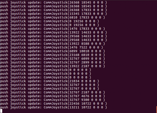
If you now move the joystick, the third terminal that runs the ComponentRosJoystick will print the respective update values:
As you can see, the joystick raw data that is provided via a ROS node can be accessed via a software component in the SmartMDSD Toolchain.
Have fun in trying out!
Further Information
- SeRoNet Mixed-Port Component for ROS (partially conformatn to RobMoSys)
Acknowledgements
The SeRoNet Mixed-Port-Component for ROS is part of the SeRoNet Tooling which is based on the SmartMDSD Toolchain. The SeRoNet Tooling is developed by the SeRoNet Project. The ROS Mixed-Port Component is developed in a joint effort by Service Robotics Research Center of Ulm University of Applied Sciences and Fraunhofer-Institut für Produktionstechnik und Automatisierung. The general concept behind a mixed-port component is an effort of the EU H2020 Project RobMoSys.
