Table of Contents
Develop Your First Software Component
This Tutorial will guide you to model, develop and compile your first software component. It will guide you to develop ComponentLaserObstacleAvoidNew Component by using readily available Domain Models.
This tutorial is also available as video tutorial.
Basic Information
| Level | Beginner |
|---|---|
| Role | Component builder |
| Assumptions | Having completed the tutorial A More Complex System using the Flexible Navigation Stack |
| System Requirements | Virtual Machine Image Installed, see ready-to-go virtual machine |
| You will learn | How to model a component How to choose the input / output ports (services) used / provided by a component How to implement a component |
Introduction
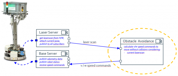
This tutorial explains how a component supplier models and implements a software component from scratch. We do this by a simple obstacle avoidance algorithm for a mobile robot. You have already seen this algorithm in operation in this previous tutorial. In contrast to the previous lesson, we now not only modify the source code within an already given software component, but we set up the software component from scratch.
- The first step is to model the component hull with its input / output ports. Ports are not arbitrarily defined by a component supplier (as then components would not be composable anymore), but they are selected from a set of already predefined service definitions. The service definitions (service for laser sensor data, service for motion commands, etc.) are part of the domain models and they are agreed, modeled, and provided to component builders by domain experts (Ecosystem Tier 2 models, see RobMoSys Wiki: Ecosystem Organization).
- The second step is to generate all the software infrastructure for your new component from the models via the SmartMDSD Toolchain.
- In the third step, you implement your algorithm and you put the source code into the component hull. We illustrate this step by implementing the obstacle avoidance algorithm which you already know from a tutorial of the previous lesson.
- The fourth step then is to compile the component. You get the binary of your RobMoSys conformant software component.
All the steps are also shown in a video.
Outlook: The next tutorial in this series of tutorials will show how to use this software component and others to compose a system.
The component that is being developed in this tutorial can also be found in the code repository.
Modeling the component
The first step in modeling a component is to open the Component Supplier (Tier 3) perspective.
- use the menu: Window → Perspective → Open Perspective → Other …,
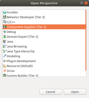
- or simply click on the Open Perspective button located at the upper right in the Eclipse window. In the next popup window, select the Component Supplier (Tier 3) perspective (see the following screenshot) and click the Open button. Please also read the new UI features HowTo for further information on the new perspectives.
We now guide you through the steps of creating a new component project for our component and naming it ComponentLaserObstacleAvoidNew.
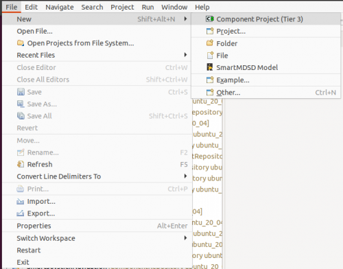
Step 1.a: Select File → New → Component Project (Tier 3)
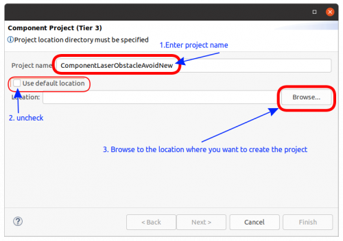
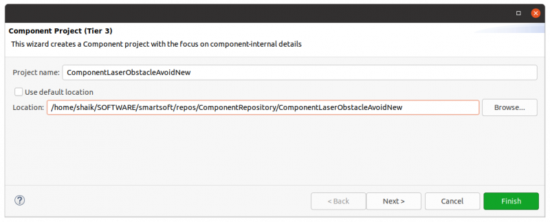
Step 1.b: We now give the project a name and we also specify the project directory. Fill in ComponentLaserObstacleAvoidNew as the project name. Then you need to uncheck the Use default location box. Click on Browse.
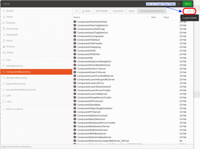
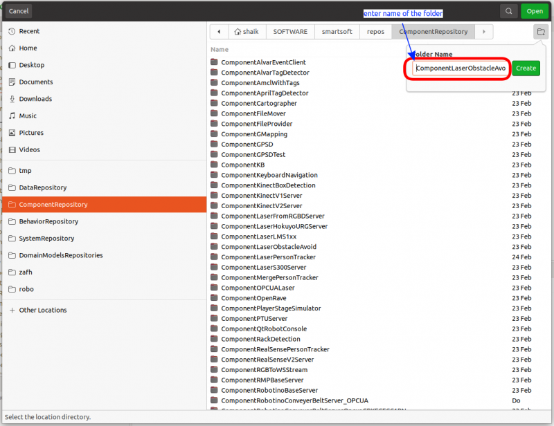
Now browse to the location $SMART_ROOT_ACE/repos/ComponentRepository/ (which is the default location for component projects). Click on the Create New Folder icon, enter ComponentLaserObstacleAvoidNew as the folder name and click create.
The project name and the project location should now look as follows:
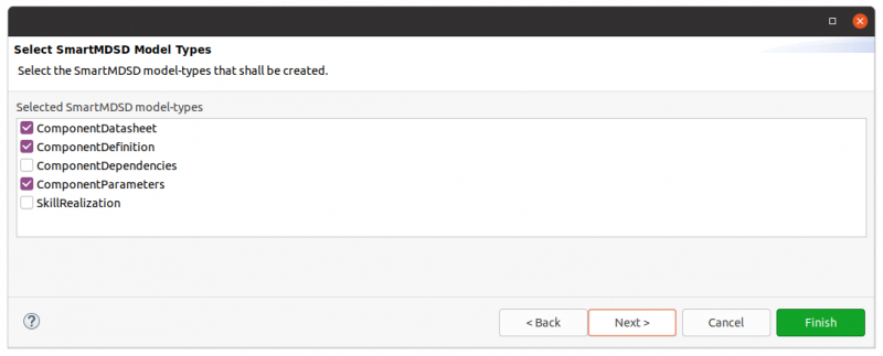
Now click Next and you end up in the following screen:
Keep the checked boxes as-is (the meaning of the different model types for a component project are explained in this tutorial (to be added)) and click Next. You now can see the Domain Models available in your workspace.
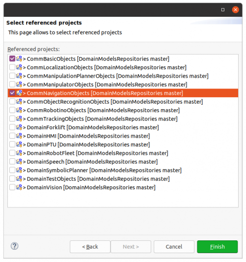
Now we select the domain models we are going to use to model our component. In the list, select CommBasicObjects and CommNavigationObjects and click Finish.
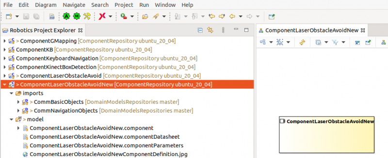
Step 1.c: The project is created and you can see the project directory structure:
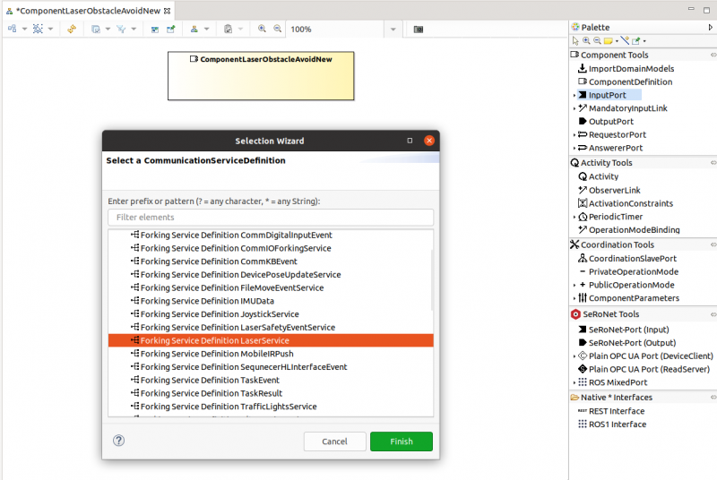
Step 1.d: Drag InputPort onto the component. This lists the available services out of which you need to select the Forking Service Definition LaserService and then click on Finish. Input ports are required services.
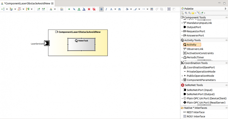
Step 1.e: You now see the component with the added Input Port which is of type LaserService. Now drag Activity onto the component and name it RobotTask. The RobotTask activity later on runs your algorithm.
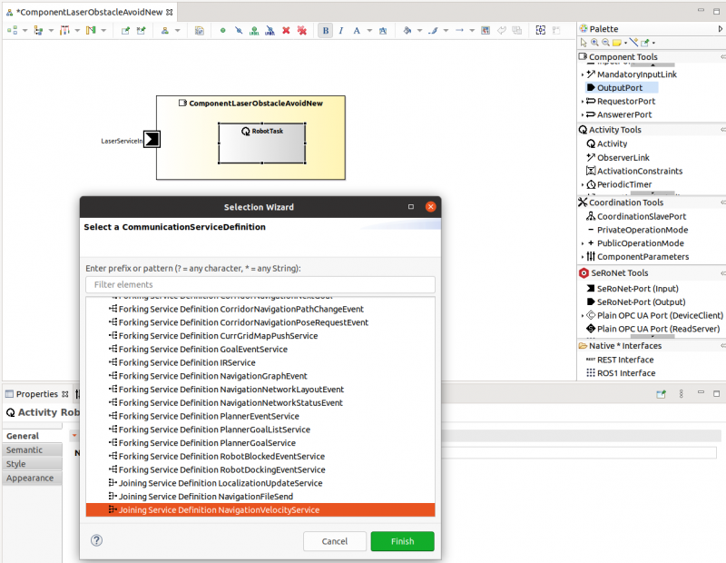
Step 1.f: Drag OutputPort onto the component. This lists the available services out of which you need to select the Joining Service Definition NavigationVelocityService and then click Finish. Output ports are provided services.
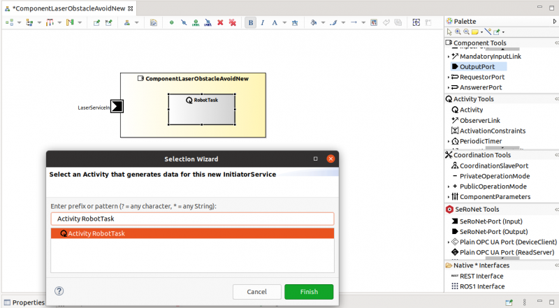
Step 1.g: A Selection Wizard lists the activities modeled in the component. Now select the RobotTask and click Finish. We now linked the output port to a source (here an activity). This is mandatory as output ports make sense only when they are “fed” from inside the component (otherwise, they are dead provided services). In our case, the RobotTask will provide speed commands (NavigationVelocity) via this output port to other components.
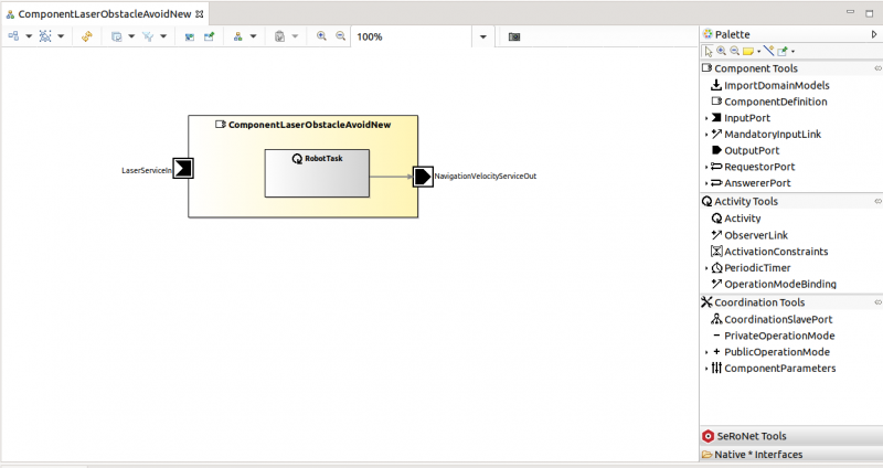
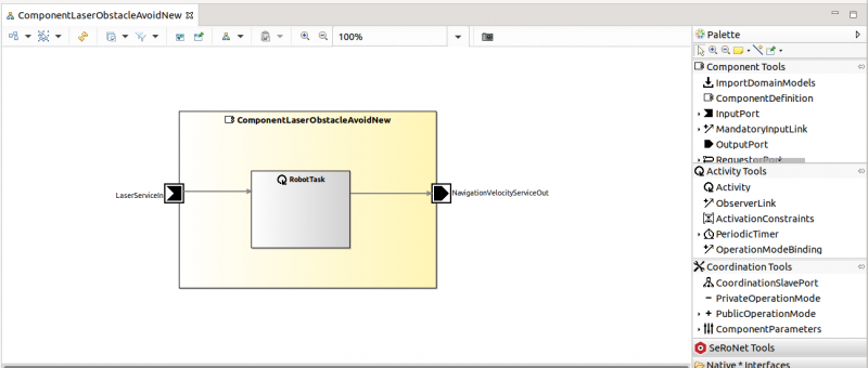
Step 1.h: Now you see that there is a link between the RobotTask and the Output port.
Step 1.i: As you can see, the LaserServiceIn is not yet connected to any task. Of course, it is the decision of the component builder (you) whether you are using an incoming service (and if yes, by which of your task(s)).
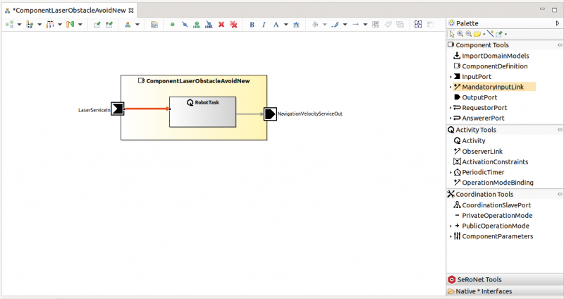
In this implementation of our component, we need the LaserData as input to calculate new speeds to command the robot such that it moves around without collisions. So, let's create a link between LaserServiceIn and RobotTask. Use MandatoryInputLink to draw a link from LaserServiceIn to RobotTask. The RobotTask can now access the incoming LaserData to calculate speed commands.
Step 1.j: Let's nicely arrange our component model.
Step 1.k:
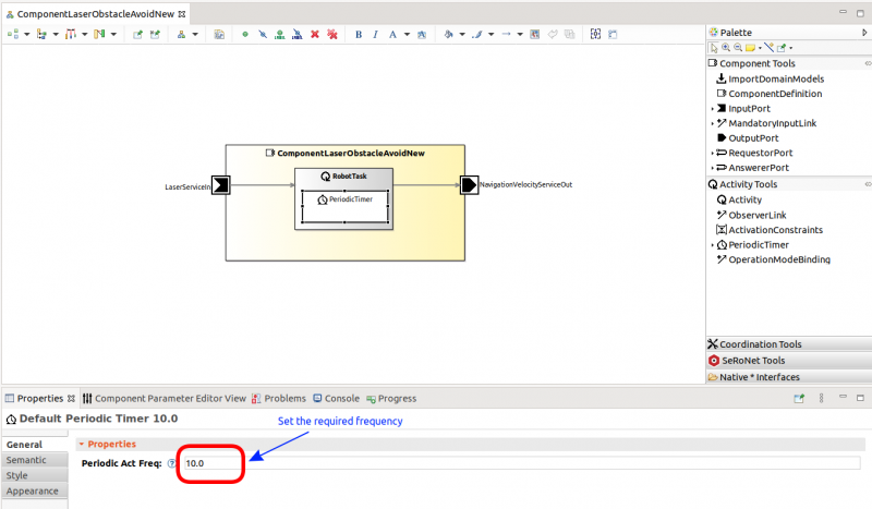
We want to have the component task to run periodically. So we add a periodic timer which triggers the task to get executed with the frequency as set in the properties. We set the frequency to 10 Hz (default values can be changed later on during the system composition).
The modeling part of the component is done.
Code Generation for the Component
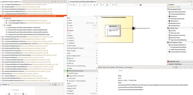
Step 2.a: We need to generate all the software infrastructure for our new component from the model. Right click on the component project ComponentLaserObstacleAvoidNew and click Run Code Generation.
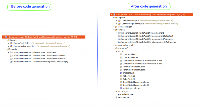
Step 2.b: The following figure shows the folder structure before and after the code generation.
The folder and content of src-gen is auto-generated. It is overwritten each time you run the code generation. So users must not modify anything in this folder. All the user contributions are always to be done in the folders without the gen extension.
The user written code resides in the src folder. The src folder also gets equipped with auto-generated code when you run the code-generator. As you see in the following steps 3.x, these auto-generated files in the src folder provide the structure and hooks for your user code. You can edit those files directly and you can add your code directly into these files.
Auto-generated files in the src folder are generated once. If there are updates in the model and you rerun the code generation, the code generator adds further files for newly added model elements. It never deletes files inside the src folder, even if the related model elements are removed from the model. Thus, user code added in the src folder and user code added to the auto-generated files in the src folder is not affected by a rerun of the code generator. If you want the toolchain to re-generate a file in the src folder, you need to delete it before running the code generator.
Implement the Business Logic
Now, let's implement the business logic of LaserObstacleAvoid that actually takes laser scans and calculates navigation commands. Basically, we are going to code our algorithm and let it then execute via the RobotTask.
Step 3.a:
We now implement the laser obstacle avoid algorithm. Of course, such an implementation is already available via the ComponentLaserObstacleAvoid component in our component repository. As this algorithm is very simple, we had been lazy and we put the algorithm into the SimpleAvoid.hh (comprising the source code, no separate cc file).
Download SimpleAvoid.hh and place it in the src folder of the component project ($SMART_ROOT_ACE/repos/ComponentRepository/ComponentLaserObstacleAvoidNew/src).
Of course, you can also implement your own obstacle avoidance algorithm!
Step 3.b:
We now connect the RobotTask activity with our implementation of our obstacle avoidance algorithm. You will see how our algorithm gets called by the RobotTask and how we can access the input port (laser data) and the output port (speed commands).
- The RobotTask.cc file contains the on_execute() method. This method gets triggered according to the configuration. In this tutorial, we modeled a periodic timer as trigger of the RobotTask activity. The on_execute() method runs once per trigger.
- From within the on_execute() method of the RobotTask activity, you can access all the ports that are linked to the RobotTask activity (see the model).
Now copy the following code snippet and put it into the on_execute() method within the RobotTask.cc file:
- be careful: as we implemented our algorithm within the SimpleAvoid.hh file, you need to include it inside the RobotTask.cc (see the first line in the below code snippet)
- RobotTask::on_execute()
#include "SimpleAvoid.hh"

//...

int RobotTask::on_execute()
{
	Smart::StatusCode status;

	// create a laser communication object and read it from the input port
	CommBasicObjects::CommMobileLaserScan laserServiceInObject;
	status = this->laserServiceInGetUpdate(laserServiceInObject);

	if(status != Smart::SMART_OK) {
		std::cerr << "Getting laser scan failed: " << status << std::endl;
		sleep(2);
		return 0;
	}

	// we got the laser scan and we now call our algorithm
	// it takes the laser scan as input and calculates translational and rotational velocities
	double translational_velocity =0;
	double rotational_velocity    =0;

	SimpleAvoid::runCycle(laserServiceInObject,translational_velocity,rotational_velocity);

        // we now fill the communication object for the velocities and
	// we write the communication object to the output port
	CommBasicObjects::CommNavigationVelocity comNavVel;
	Smart::StatusCode status_nav;

	comNavVel.set_vX(translational_velocity, 0.001);
	comNavVel.set_omega(rotational_velocity);

	std::cout << "translational v : " << translational_velocity	<< std::endl;
	std::cout << "rotational v    : " << rotational_velocity	<< std::endl;

	status_nav = this->navigationVelocityServiceOutPut(comNavVel);

	if(status_nav != Smart::SMART_OK) {
		std::cerr << status << std::endl;
		std::cout << "Some Error in the Conection as status is not ok " << std::endl;
		sleep(1);
	} else {
		std::cout << "Updating Velocity " << comNavVel << std::endl;
	}

	return 0;
}
//...
Compile the Component
Now you are done with implementing a component. You need to compile it before you can use it.
- Right-click on your component project → Build Project
You have now successfully completed the tutorial on developing the ComponentLaserObstacleAvoid.
What to do next?
You can proceed with the next tutorial Develop Your First System by Composing Software Components to see how to compose your component to a system and running the system.
This tutorial assumed the existence of the service definition “NavigationVelocityService” and its according communication object. To see how these can be created as Tier 2 domain models, see Develop Your First Domain Model.

