Table of Contents
Map a New Environment by Driving Around with a Joystick or via Keyboard
Create a map of a new environment by driving around with a joystick or via a keyboard. The map can be used with the flexible navigation stack.
Basic Information
| Level | Beginner |
|---|---|
| Role | System builder, but also other roles like experienced users |
| Assumptions | Having completed the tutorial Deploy a Simple System onto a P3DX (or a Robotino) |
| System Requirements | Virtual Machine Image Installed, see ready-to-go virtual machine |
| You will learn | - how to generate a 2D map of the environment |
| Options | - SystemWebotsGmapping (any mobile robot with a laser ranger) |
Introduction
This tutorial guides you through the steps to create a 2D map of the environment. The 2D map is the representation of the environment used by a robot for autonomous navigation, e.g. via the flexible navigation stack. The result of the mapping process is an Occupancy Grid Map.
- The map is built using Gmapping
- Laser-based SLAM (Simultaneous Localization and Mapping) via a highly-optimized Rao-Blackwellized particle filer
- The map can then be used within the flexible navigation stack:
- AMCL (Adaptive Monte-Carlo Localization) which tracks the pose of a robot against a known map
- SmartMapperGridMap (initial map of the environment for navigation)
We illustrate the mapping of an environment in the Webots simulator via a mobile robot equipped with a laser scanner. However, the same procedure can be used with physical mobile robots with a physical laser scanner to map the real-world environment.
Overview on the Steps
The next sections guide you through the following steps:
- first, we will deploy and start the mapping system project
- then we will manually drive around the robot using the joystick
- while we drive around, the Gmapping SLAM component (simultaneous mapping and localization) receives laser scans and odometry information and incrementally builds the map of the environment.
- finally, we save the map.
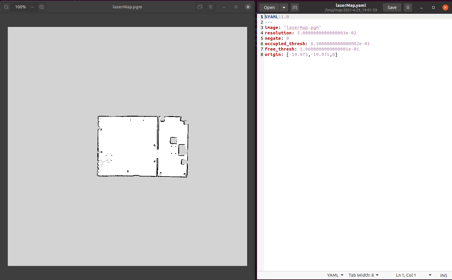
The output from this mapping process is a gray-scale image (e.g. laserMap.pgm) which contains the map of the environment and a configuration file (e.g. laserMap.yaml) which contains the information to interpret the image.
Both these files are needed by the components SmartAmcl and SmartMapperGridMap of the flexible navigation stack for navigating a mobile robot.
The System Architecture
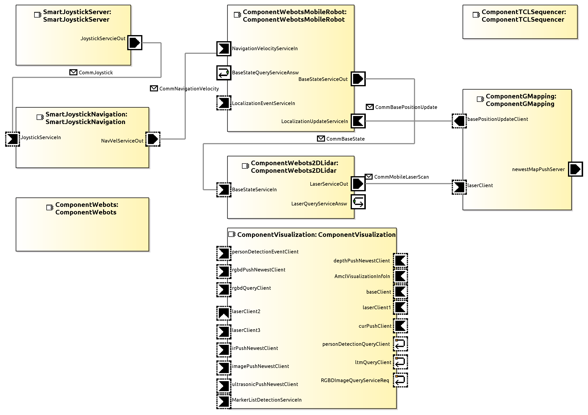
The system architecture used for mapping the environment in the Webots simulator is as follows:
- ComponentGMapping: Builds an occupancy grid map of the environment by receiving laser scans and odometry data from robot.
- SmartJoystickServer: Reads data from a joystick and generates CommJoystick messages.
- SmartJoystickNavigation: Receives CommJoystick messages and converts them into velocity commands for a robot.
- ComponentVisualization: Utility component to visualize data (e.g., map, laser scan, robot pose).
Preparation Steps for Mapping
Configuring the system project
Step 1.a: In SystemWebotsGmapping project, open the model folder and open SystemWebotsGmapping.systemParam file. Make sure that the parameters of the components are configured correctly.
WorldPathparameter inGeneralinternal parameters ofComponentWebotsspecifies which webots world file(*.wbt) should be loaded in the simulator. This world file must contain a mobile robot with a laser ranger. Configure the parameters of ComponentWebotsMobileRobot and ComponentWebots2DLidar according to the robot, laser used in the simulation.
deviceparameter inGeneralinternal parameters ofSmartJoystickServermust contain the joystick device path(e.g., “/dev/input/js0”).
Deploy the mapping system project
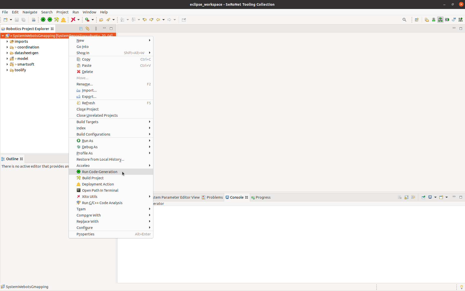
Step 2.a: Right click on the SystemWebotsGmapping project → Run Code-Generation
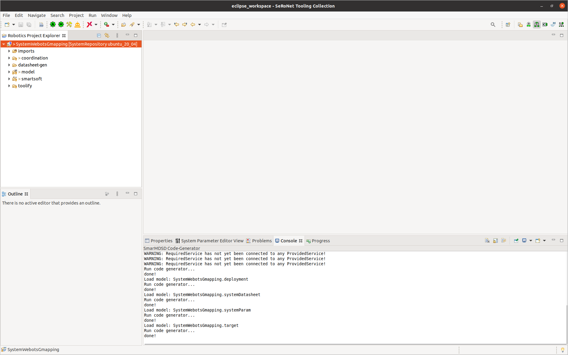
Make sure that there are no errors during the code generation.
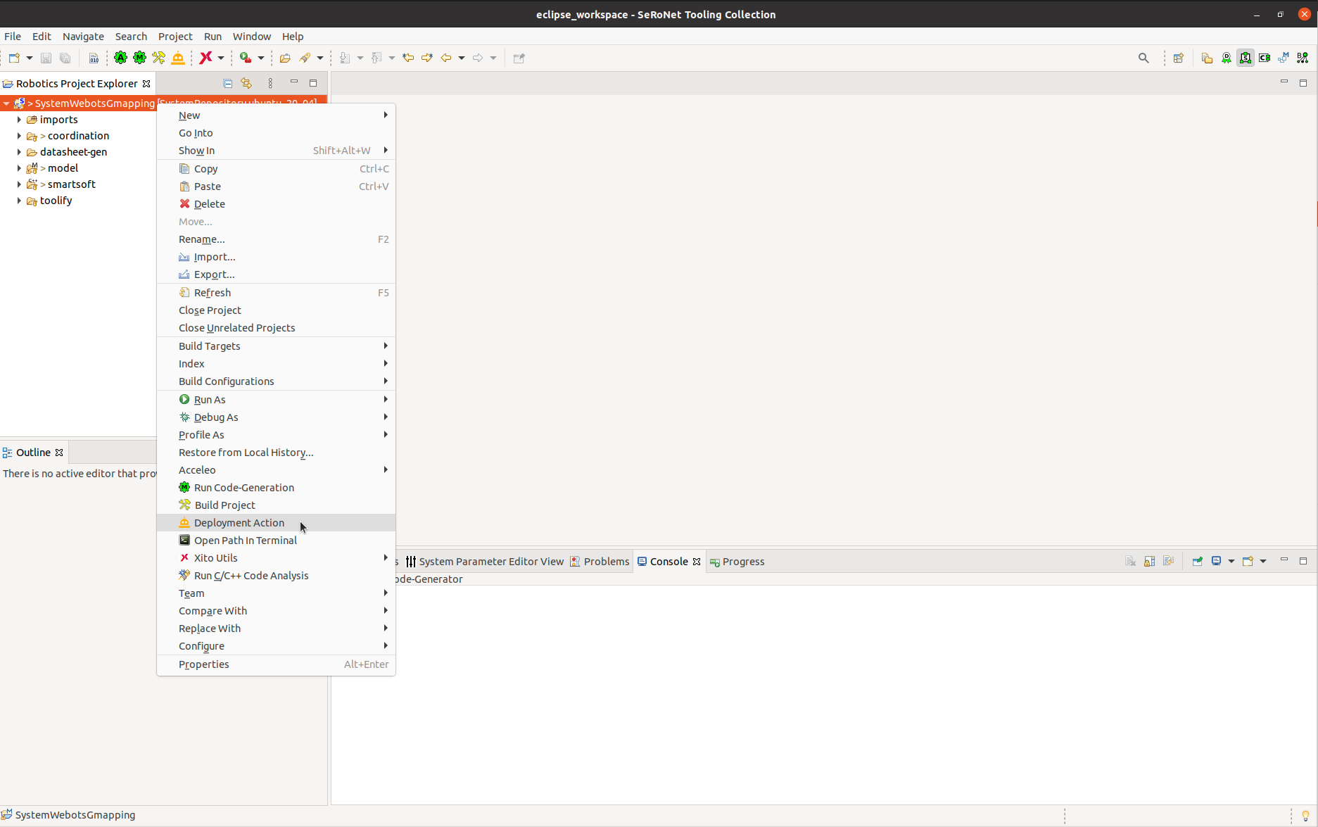
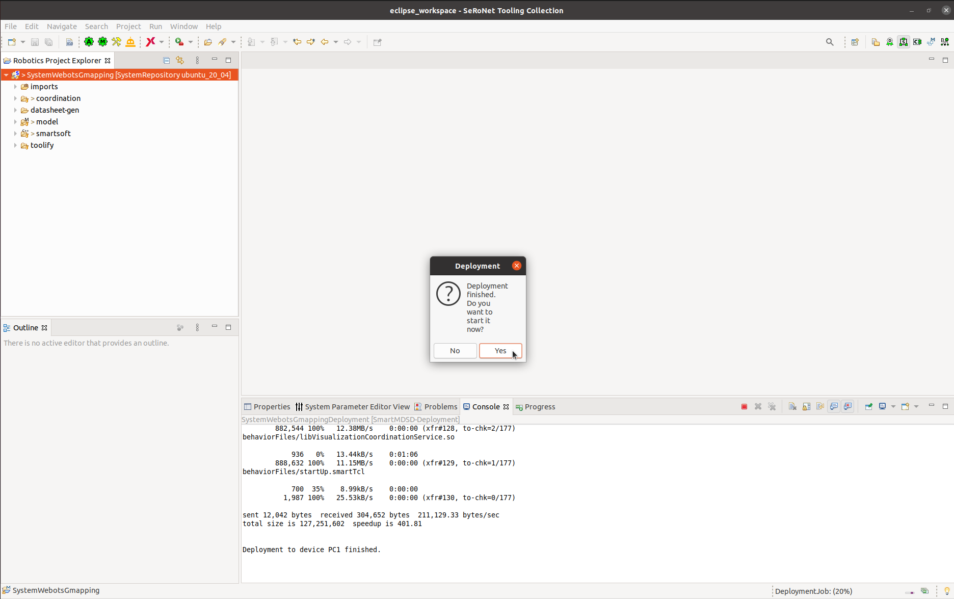
Step 2.b: We now deploy the system by clicking the Deployment Action from the right-click menu of the project:
It depends on your configuration whether you are being asked for credentials of the configured login account. Finally, you see the following pop-up window which tells you that the deployment was successful:
Step 2.c: You can use either a joystick or the keyboard to drive the robot. If you want to use a joystick, make sure that you have connected the joystick to your computer. It is important that the joystick is connected before starting the system.
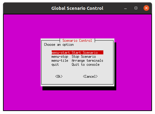
You can now start your system by clicking Yes. A terminal window will open and show the scenario control menu. Choose menu-start Start Scenario.
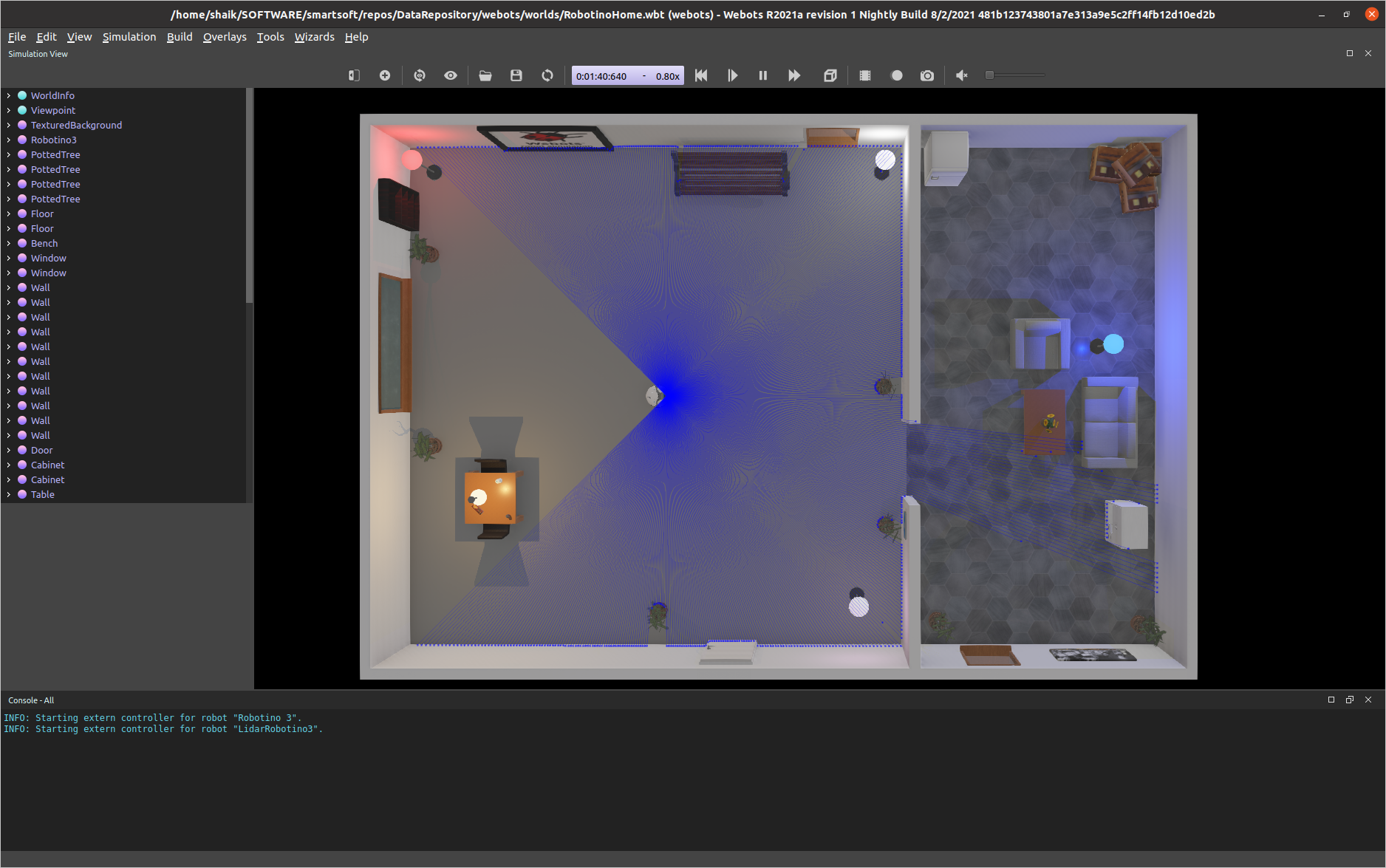
Step 2.d: Wait until the world is fully loaded in Webots.
Placement of the robot in the environment
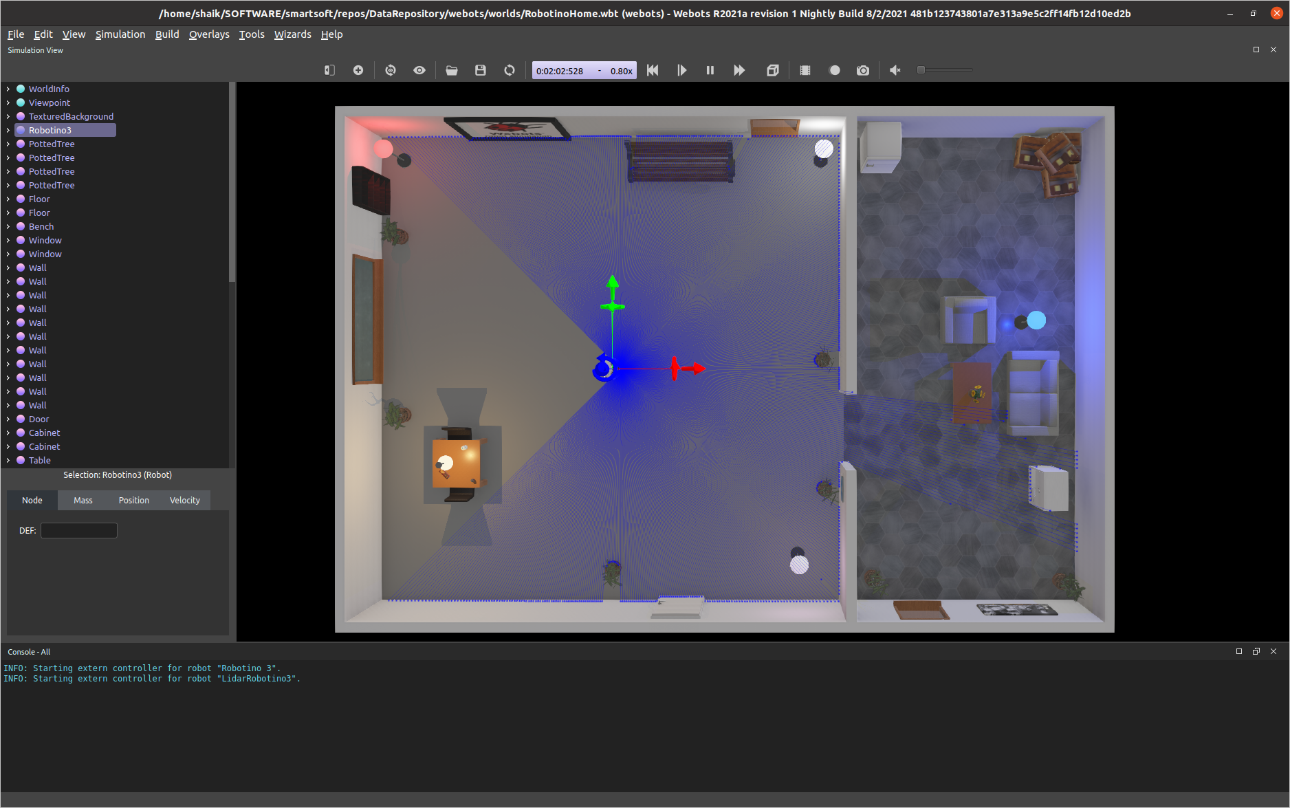
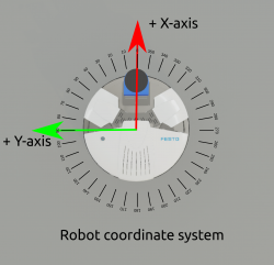
Step 3.a: Click on the robot to see the coordinate system of the robot. This robot location will be the origin of the map you are going to create.
Step 3.b: Now check the position and heading of the robot. You can move the robot to any location and you can set it to any heading. This position and heading will be the origin of the map which is going to be created.
The initial position of the robot is very important for mapping. This initial position is used as origin of the map (i.e. x=0.0, y=0.0, heading = 0°) by the mapping algorithm. A right-handed coordinate system is the standard used for representing the coordinate system of the robot. Below figure shows the coordinate system of the robot:
Mapping the environment
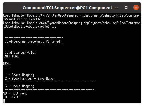
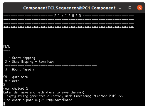
Step 4.a: Look for the terminal which contains the ComponentTCLSequencer.
In the menu, select “1 - Start Mapping” to start the mapping.
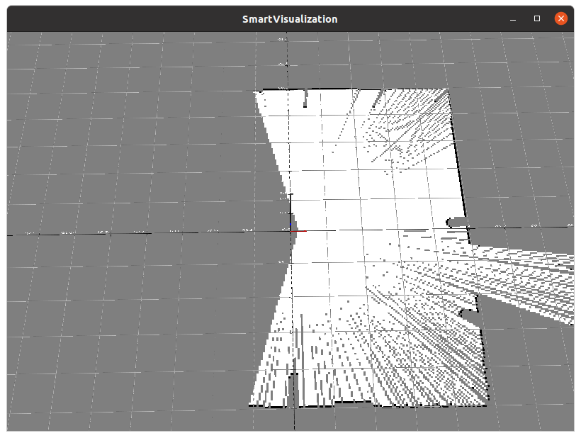
Step 4.b: Look for the SmartVisualization window, it shows the map that is built so far. You can use your mouse to zoom and pan the view of the map in the SmartVisualization window.
Step 4.c
- Option I: Driving with the Joystick: Use the joystick to drive the robot around in the environment and keep observing the
SmartVisualizationwindow. Drive the robot to cover all the area which you intend to use for navigation.
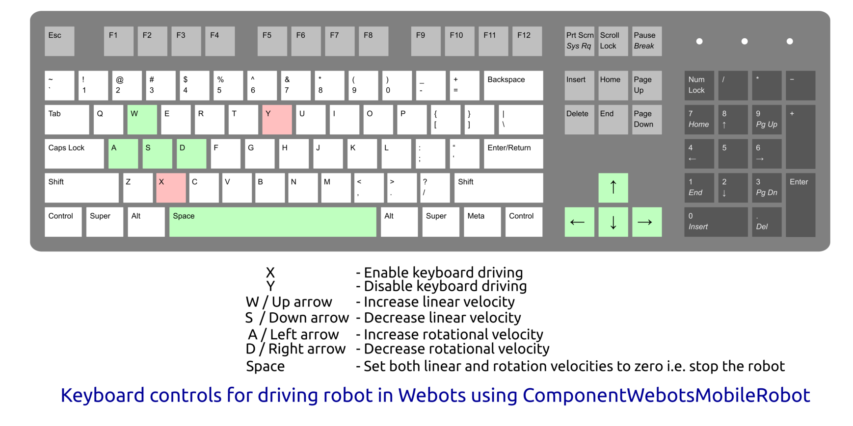
- Option II: Driving with the Keyboard:
- Make sure that the keyboard focus is the Webots application.
- Enable the keyboard driving by pressing “x” in the keyboard.
- Now you can drive the robot using arrow keys or WASD keys. Use the space key to stop the robot. Keyboard controls are shown below :
- Driving Tips for better Mapping:
- directly after you started mapping, it helps to rotate the robot on the spot for 360° at the origin
- the same can be done at junctions in corridors etc. in order to better grasp full scenes
- be aware that faster rotations can cause problems so it is better to make slower rotations
- the environment should be static while mapping. However, small dynamic changes like humans walking in the scene can be handled
Step 4.d: Finally stop the mapping and save the map by selecting “1 - Stop Mapping - Save Maps” in the ComponentTCLSequencer. You will be asked to enter the path to store the map, you can enter the desired path or just press enter.
By default the generated map is stored in the folder “/temp/map-xxxx-x-xx_xx-xx-xx/”. This folder contains two files, laserMap.pgm and laserMap.yaml. The file laserMap.pgm is the generated grid map of the environment and laserMap.yaml is the specification of the generated map. The file laserMap.yaml contains the origin of the map and values specifying the size of a pixel in meters. laserMap.yaml must be available to interpret the generated grid map.
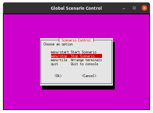
Step 4.e: Finally stop the system by selecting menu-stop Stop Scenario in the Gloabl Scenario Control window. It stops and closes all the components and the Webots simulator.
Post-Processing the Map
Any image processing tool (e.g. GIMP) can be used to post-process the generated map. There are several good reasons to do this, some of the common scenarios are the following:
- since it is about 2d mapping, some places which appear in the map as of being free are in the real-world occupied by obstacles
- e.g., tables and chairs in the environment are mapped as four points - i.e. the legs - and the table/chair top show up in the map as free space as the laser can see only the lower part of the table/chair.
- if such maps are used for navigation, a robot will try to drive beneath the table/chair.
- glass doors and walls are not mapped well into the map because of the laser reflective properties.
- states of doors in the environment might be different during the mapping and navigation, i.e. the door is opened during the mapping and is closed during the navigation or vice versa.
- it is better to represent doors as open space as then they can be used for navigation. It is then the navigation stack which perceives the true current state of a door when the door comes into the field of view.
What to do next?
Now you can proceed with tutorial Symbolic Names for Rooms - How to Update the Knowledge Base

