Table of Contents
A More Complex System using the Flexible Navigation Stack
Explore and run a more complex system in simulation: the flexible navigation stack that that is in use with real-world service robots.
Basic Information
| Level | Beginner |
|---|---|
| Role | System builder, but also other roles while browsing through the system's building blocks |
| Assumptions | Having completed tutorial Simple System: Laser Obstacle Avoid |
| System Requirements | Virtual Machine Image Installed, see ready-to-go virtual machine |
| You will learn | How you can use a complex and prebuilt system How components interact with each other based on services and how these are wired |
| Options | - SystemWebotsRobotino3Navigation (Robotino in THU Campus Environment) - SystemWebotsP3dxNavigation (P3DX in THU Campus Environment) - SystemWebotsTiagoNavigation (Tiago in THU Campus Environment) - SystemWebotsLarryNavigation (Larry in THU Lab Environment) |
Introduction
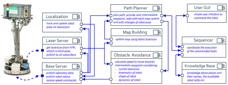
This tutorial is an example of a more complex system project which involves a whole bunch of software components. The system comprises components for path planning, for map building, for obstacle avoidance and motor control, for localization, for task coordination, and for world models. The system features the flexible navigation stack which is in use in real-world service robots.
The following sections will guide you through all necessary steps to run a system project. We have a look at the different system level models (system component architecture model, target platform model, deployment model) and explore the involved components.
System Architecture Model
To open the system project, double click on the project SystemWebotsRobotino3Navigation.
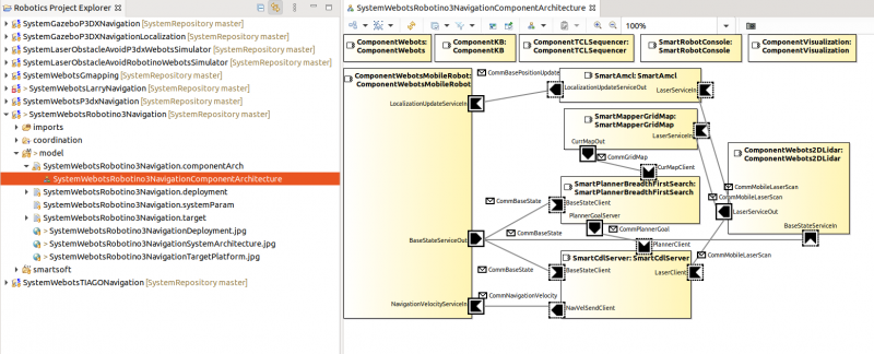
To explore the system composition of this project, you have two different options. Double-click one of the items highlighted in the figure to open the system component architecture:
The system architecture model comprises instances of software components and the connection of their provided / required services. In this example, the following components are arranged:
- SmartMapperGridMap: probabilistic 2D grid map (long term map, current map): maps the environment
- SmartPlannerBreadthFirstSearch: breadth first search algorithm to find a path in a grid map, provides intermediate waypoints to the CDL motion execution component
- SmartCdlServer: drives towards intermediate waypoints as received from the path planner. It takes into account the robot's kinematics, dynamics, and its shape
- SmartAmcl: probabilistic localization of the robot
- ComponentTCLSequencer: coordinates the exeuction of the commanded tasks
- ComponentKB: the knowledge base with the names of the various places
- SmartRobotConsole: simple user interface to command the robot
- ComponentWebots: the interface to the Webots simulator
- ComponentWebots2DLidar: the interface to the Webots simulator laser ranger
- ComponentWebotsMobileRobot: the interface to the Webots simulator mobile robot
Target Platform Model
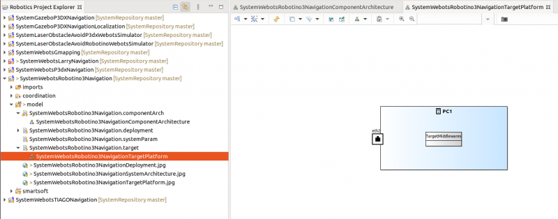
The figure below shows the target platform model of the system. This model configures the runtime environment and hardware details.
Deployment Configuration
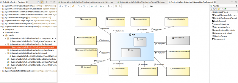
The Deployment model shows the mapping of software artefacts to the hardware platform. I.e. it models which artefact will be “deployed”/transferred to and run on which platform. In our example, we will deploy to the local system. In real-world examples, we can deploy to remote targets and distribute a system to multiple targets.
Running the System
Deployment
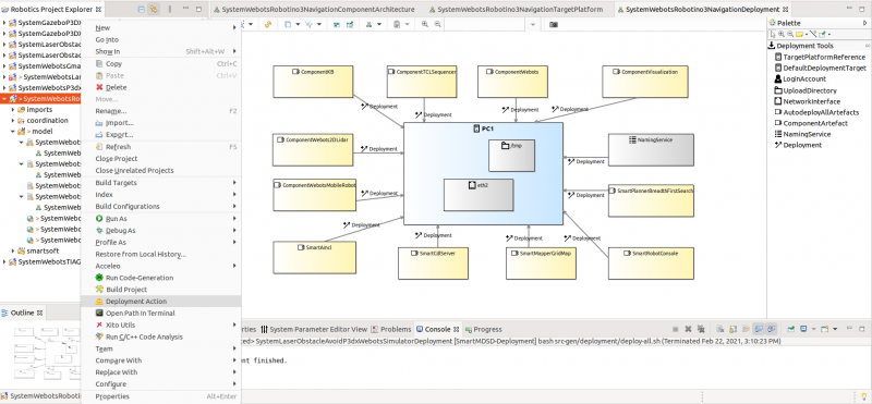
As shown in the snapshot below, right click on the project and select Deployment Action. This will collect and copy the software artifacts and transfer them to the target/robot.
Starting the System: The THU Campus World Scenario
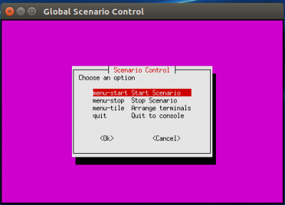
After the deployment is finished, you can start the scenario. Click “yes” in the dialogue that pops up. It will launch the scenario control menu as shown in below figure:
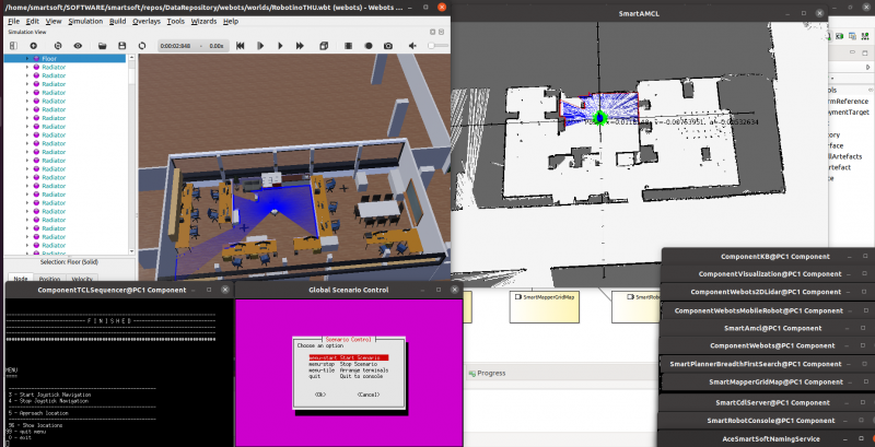
Select menu-start Start Scenario and press Enter to start the execution of the project. It will launch all the components and the simulator.
Look for the terminal which contains the ComponentTCLSequencer.
In the menu, select “5 - Approach location” and enter one of the offered names for locations.
Now, the robot navigates to this destination and stops there.
Further Information
- Read more About the SmartSoft World
- Learn more about the Flexible Navigation Stack that was used in this scenario: RobMoSys Wiki: Flexible Navigation Stack
- See videos: all moving robots are based on the navigation stack that is shown in this tutorial
What to do next?
The next tutorial is Develop Your First Software Component , which will guide you for creating your first own Component step by step.
Optional: A realistic setting of the very same navigation stack that was presented here is demonstrated by the RobMoSys Gazebo/TIAGo/SmartSoft Scenario using the PAL Robotics TIAGo service robot. Find it at the RobMoSys Wiki. You may also want to explore it!
