Table of Contents
Simple System: Laser Obstacle Avoid
In this tutorial, you explore and run a simple obstacle avoidance system: a mobile robot with a laser ranger moves around without collisions in a simulation. By a simple—but realistic—example you get first hands-on experience with the SmartMDSD Toolchain.
Basic Information
| Level | Beginner |
|---|---|
| Role | System builder and component builder |
| Assumptions | none |
| System Requirements | Virtual Appliance installed, see ready-to-go virtual appliance |
| You will learn | - how to start/deploy a readily available set of components using a simulator - how to look at the source code inside a software component - how to compile a software component after modifying its source code |
| Options | - SystemLaserObstacleAvoidP3dxWebotsSimulator - SystemLaserObstacleAvoidRobotinoWebotsSimulator |
Introduction
This tutorial guides you through the SmartMDSD Toolchain by a simple example: we move around a robot in simulation with a simple laser-based obstacle avoidance algorithm. We explore in the SmartMDSD Toolchain the software component for obstacle avoidance and the obstacle avoidance algorithm inside the software component. This gives you first hands-on experience with the SmartMDSD Toolchain.
We use an already existing software component project “ComponentLaserObstacleAvoid” as well as the already existing system project “SystemLaserObstacleAvoidP3dxWebotsSimulator”.
- SystemLaserObstacleAvoidP3dxWebotsSimulator: System with the Webots Simulator, a P3DX mobile robot and a laser ranger.
- ComponentLaserObstacleAvoid: Software component which implements a simple reactive obstacle avoidance algorithm. It periodically receives laser range scans, calculates steering commands and provides these to the mobile robot (simulator) for execution.
System Architecture
Before we start the system, we will take a look at the architecture.
First, open the project if necessary: Right-click on “SystemLaserObstacleAvoidP3dxWebotsSimulator” in the “Project Explorer” and select “Open Project”.
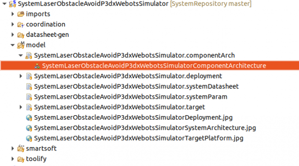
Open the Component Architecture to explore the system. It is named SystemLaserObstacleAvoidP3dxWebotsSimulatorComponentArchitecture. Double click the highlighted entry as indicated in the below figure:
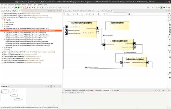
As you can see in the below picture, the system contains the two components: one to represent the simulator and one for obstacle avoidance. Both components provide or require services. Two pairs of component ports are connected. The obstacle avoidance component will receive laser scans from the simulated robot, calculate commands, and provide/send them as navigation velocity commands to the simulated robot.
We will later explore and modify the obstacle avoidance algorithm.
Executing the System
Deploying and Starting the System
To run the system, we need to deploy it and run the components.
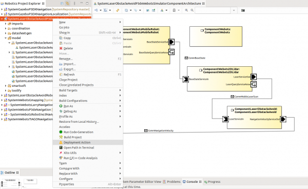
The deployment copies / transfers all needed parts of the system onto the target machine. In this tutorial, it is your computer. Right-click on the system project and click on Deployment Action.
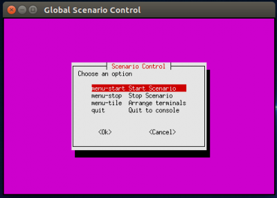
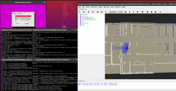
The system is now ready to start and you will be asked to execute it. Choose Yes in the popup dialogue to start the system. A terminal window will open and show the scenario control menu:
Choose menu-start to start the scenario. Further terminals open automatically (one per component and an additional one for the naming service). Note that they may not be visibile initally in case they overlap.
Now, all software components and the simulator start running. You will see the GUI of the simulator showing the robot moving around in the hospital world (famous benchmark map from Player/Stage):
Hints on how to use the simulator
- you can move / rotate the robot by selecting it and then use the arrows that pop up
- you can zoom in / zoom out by the wheel of the mouse
- you can move the map and any object by selecting and dragging it (left mouse button)
Stopping the System
To stop the simulation and all components, select the following options in the scenario control window/menu :
- Choose menu-stop to stop the scenario and all the software components
- Choose quit to quit the scenario (quit includes menu-stop)
All components and the simulator shutdown in a coordinated way. Only one window stays open which you need to close manually.
Always shutdown the components via menu-stop or quit. This does all the house-keeping in a coordinated way. Do not close any window (besides the above mentioned last remaining window) manually as this breaks needed house-keeping activities.
Exploring the Component for Obstacle Avoidance
To better understand the components in this scenario, we will explore the software component ComponentLaserObstacleAvoid. We will inspect it at the model and source code level. We will run the build process from model transformation, code generation, and compilation and test it in our system.
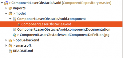
Open the software component model by double clicking one of the entries highlighted in the below image:
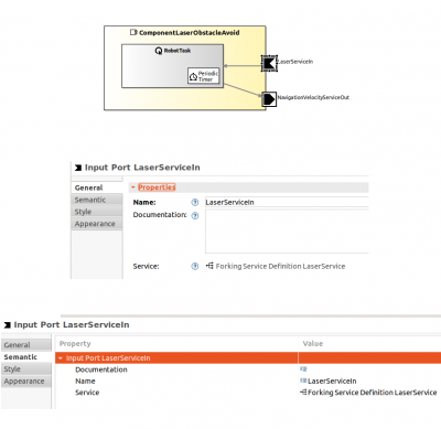
The model of the obstacle avoidance component looks as follows:
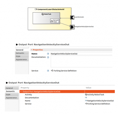
The component has one activity named as RobotTask which is connected to two component ports. One port is an input port for the laser service LaserServiceIn. The other port is output port for NavigationVelocityServiceOut. Click on a port and open the properties view to see its details as shown in the below figure. This port realizes the service definition ForkingServiceDefinition LaserService.
The algorithm calculates movements based on the laser scan and provides these movements as navigation velocities to command the robot. Open the output port properties, and you can see it realizes JoiningServiceDefinition NavigationVelocityService.
Modifying the Algorithm
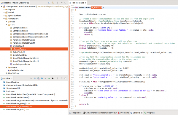
This algorithm is implemented in an activity. Its model representative is the RobotTask. To open the source code of the RobotTask, open the file /ComponentLaserObstacleAvoid/smartsoft/src/RobotTask.cc. The method RobotTask::on_execute() holds the implementation of the algorithm. It first receives laser scans,then calculates new navigation commands and finally sends them to the robot base.
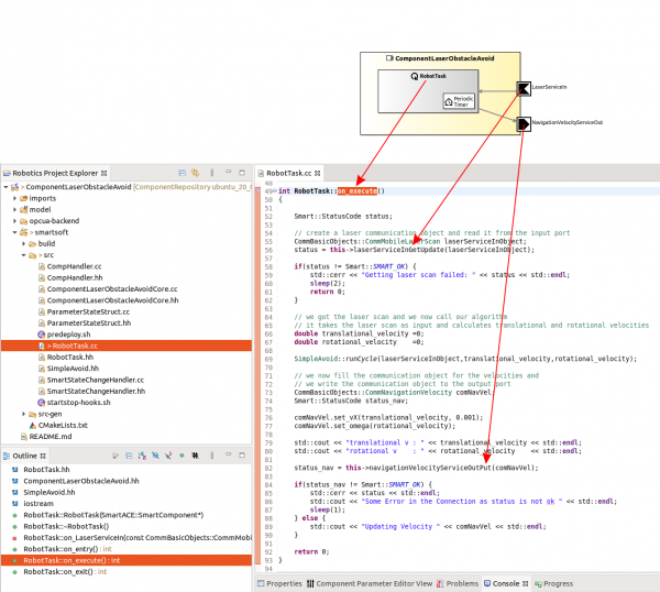
Now read through the source code to understand the algorithm. Note how the algorithm receives scans from a port of the component and how it provides motion commands to a port of the component.
The following figure describes the relation of the ports and activity of the component model to the source code that implements the algorithm in the RobotTask.
You may now modify the source code and enhance the algorithm.
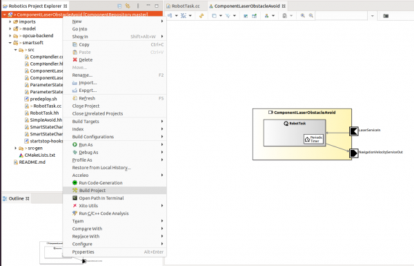
After modifying the source code, you need to compile the component:
- Right click on project ComponentLaserObstacleAvoid → Build Project
To test your improved component you need to deploy and run the system project where this component is included. You have learned how to do this in the first part of the tutorial.
Further Information
- Component descriptions ComponentWebots and ComponentLaserObstacleAvoid
- Read more About the SmartSoft World
What to do next?
Please proceed with the next tutorial (A More Complex System using the Flexible Navigation Stack) to have a look at a more complex system. You can then also check further tutorials for learning “how to develop your own Component and System”.

