Table of Contents
Deploy a Simple System onto a P3DX (or a Robotino)
Deploy the reactive navigation (laser obstacle avoid) onto a physical robot (Pioneer P3DX or Robotino).
Basic Information
| Level | Beginner |
|---|---|
| Role | System builder |
| Assumptions | having completed the tutorial Simple System: Laser Obstacle Avoid |
| System Requirements | access to a physical P3DX mobile robot with a SICK LMS200 laser ranger (or a Robotino mobile robot with a LMS100) Virtual Machine Image installed, see ready-to-go virtual machine Real robots equipped with SmartSoft runtime environment, see real robot runtime environment |
| You will learn | - how to deploy a system to a physical robot via the SmartMDSD toolchain - how to start the deployed system, run the physical robot, and stop the system |
| Options | - SystemP3dxLaserObstacleAvoidRealWorld - SystemRobotinoLaserObstacleAvoidRealWorld |
Description
This tutorial guides you through the steps of deploying a readily configured system onto a physical Pioneer P3DX robot. We use the now already well-known example of reactive navigation (a mobile robot with a laser scanner and a simple obstacle avoidance algorithm, see Simple System: Laser Obstacle Avoid and Develop Your First System by Composing Software Components).
As reactive navigation is independent of specific maps and coordinate systems references, you can run it in your environment as well. Of course, the pre-configuration of the system comprises parameters specific to the Service Robotics Research Lab of Technische Hochschule Ulm (accounts on the robot, IP adresses). You learn where you find various settings that you need to adjust to your robot.
So, if you
- have access to a Pioneer P3DX robot with a SICK LMS200 laser ranger
- installed Ubuntu 20.04 LTS 64 bit on the computer on-board the Pioneer P3DX robot
then you can proceed with the next steps in this tutorial. See also
The Laser Obstacle Avoid System
System Architecture View
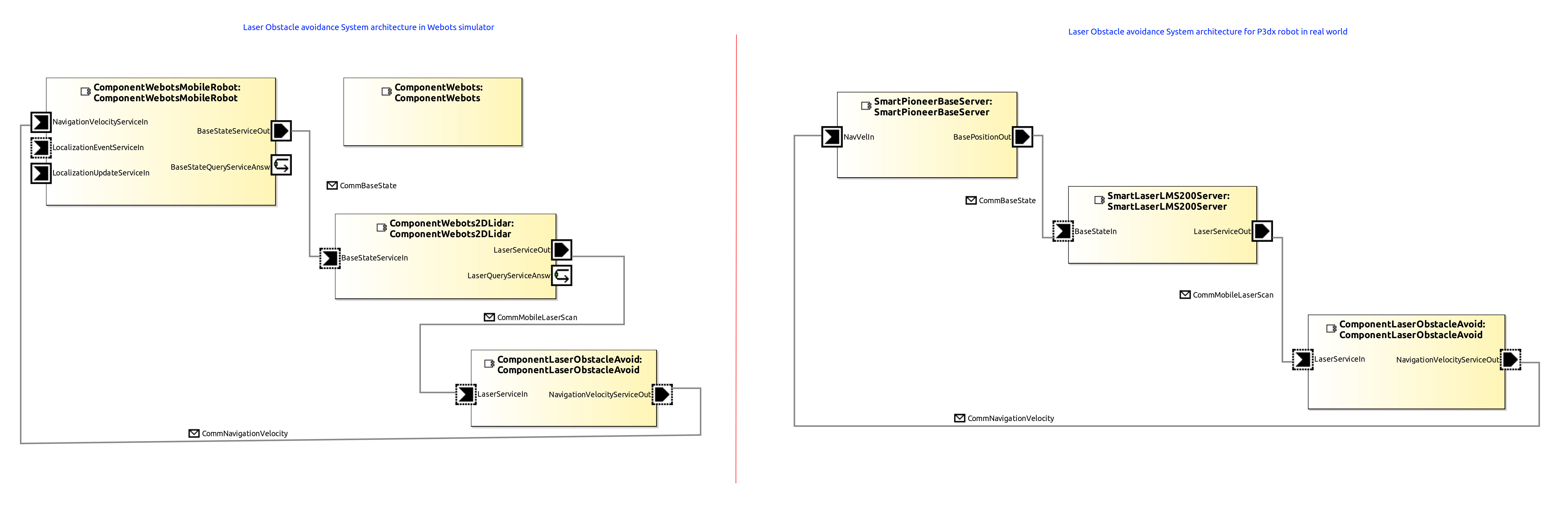
Instead of using the Webots simulator and instead of deploying the system to your PC, we now deploy the components onto a physical robot. For this, we replaced in our system the simulator components (ComponentWebots, ComponentWebotsMobileRobot, ComponentWebots2DLidar) by the components for the physical robot (SmartPioneerBaseServer, SmartLaserLMS200Server).
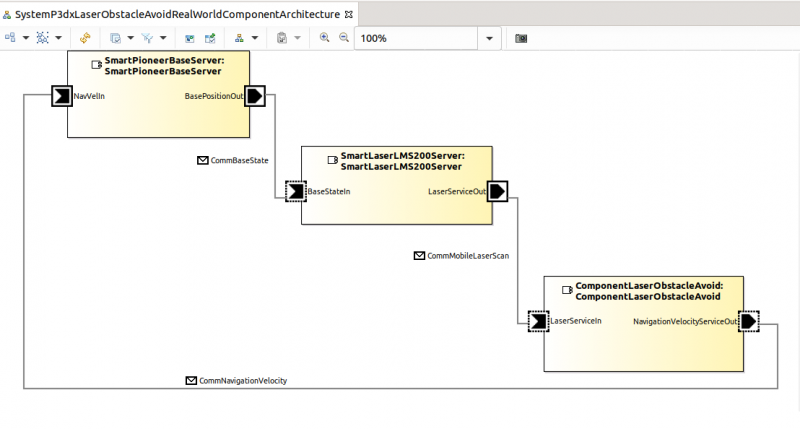
Step 1: Open the project SystemP3dxLaserObstacleAvoidRealWorld and you can see the components for the physical robot and the laser obstacle avoid component. The laser obstacle avoid component is not changed at all (even the binary is the same as in e.g. Simple System: Laser Obstacle Avoid). The services of the laser obstacle avoid component are now just connected to services of components for physical devices (SmartPioneerBaseServer, SmartLaserLMS200Server) instead to services of components for simulated devices (ComponentWebotsMobileRobot, ComponentWebots2DLidar).
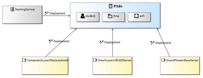
Target Platform View
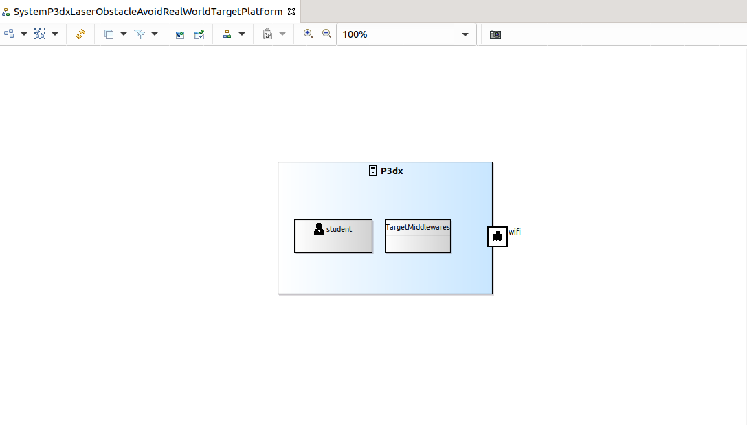
The figure below shows the target platform configuration. As we are deploying the components onto a physical robot, details of the computer on-board the physical robot need to be specified (you might want to check the target platform view in Develop Your First System by Composing Software Components for explanations).
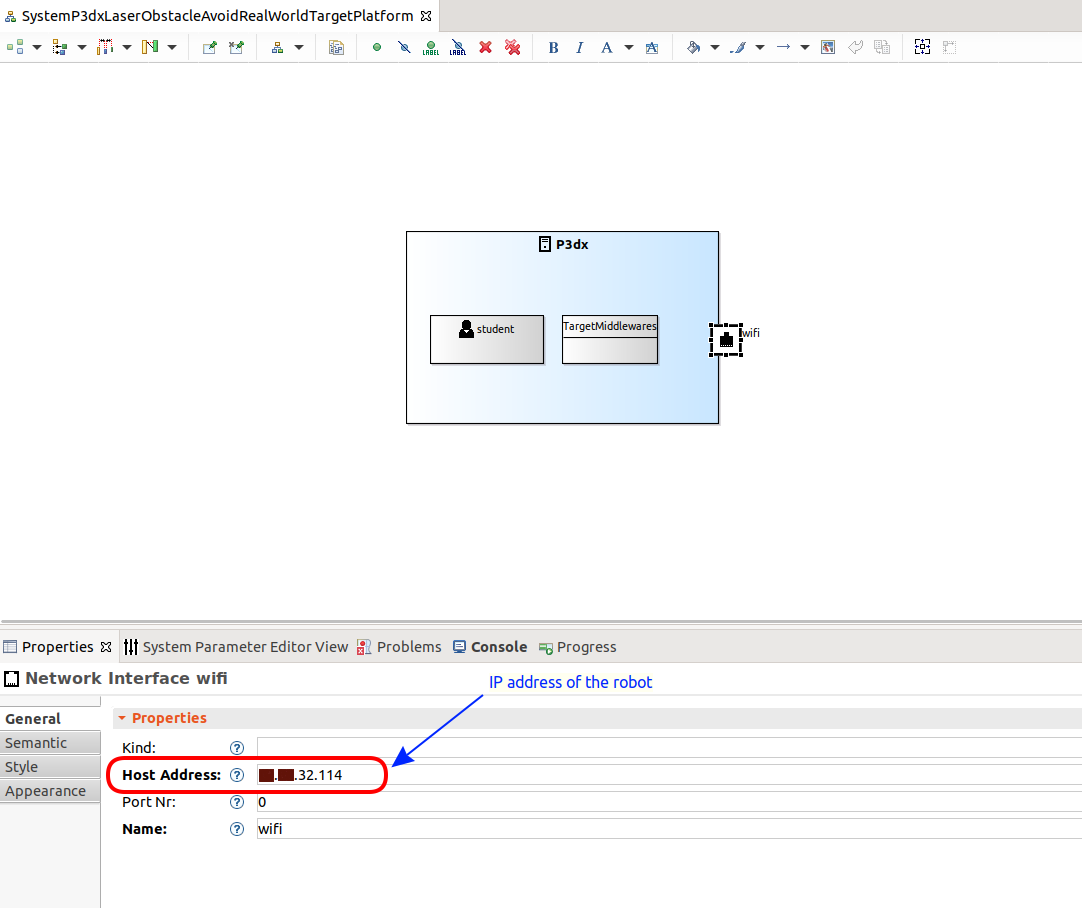
Details of the Network Interface
Step 2: We need to provide the network interface in order to be able to reach this target platform. Host address (IP address of the robot) and the name of the network interface are used and type and port number are optional.
Deployment View
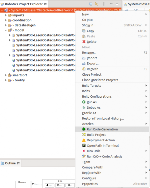
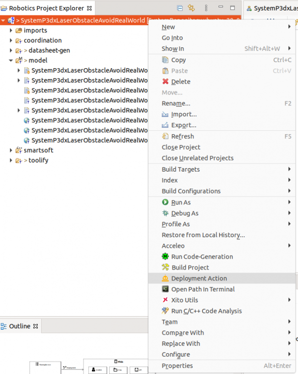
Deployment
Step 3: Deploy the system.
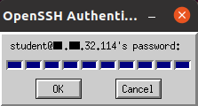
Step 4: You are now prompted for a password. We configured the system to use the login Student, for which the password is student. Just enter the password and the deployment gets completed.
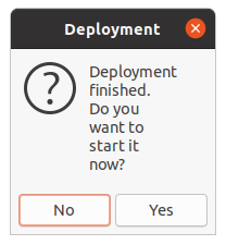
Step 5: Now a message box apperas and asks whether you want to start execution. Answer No.
Start, Run and Stop the System
Check for VNC Installation in your System
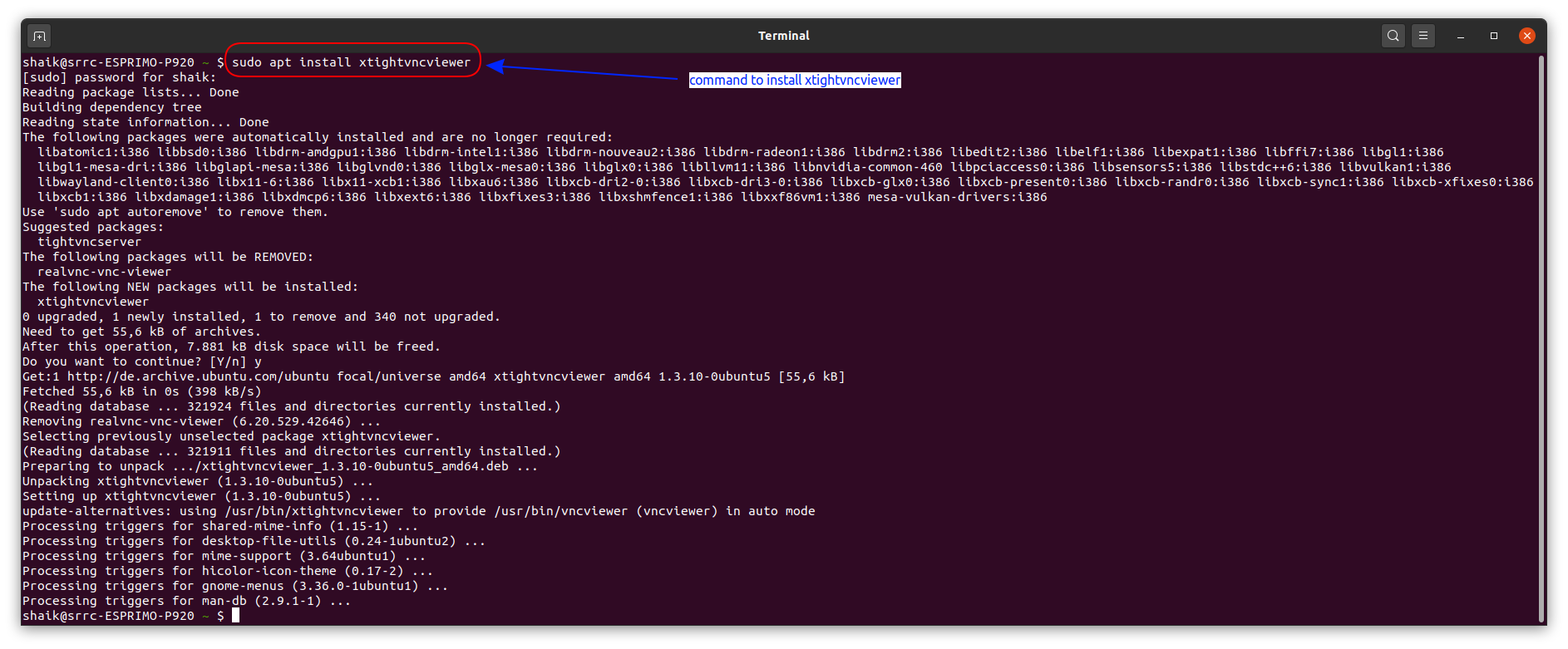
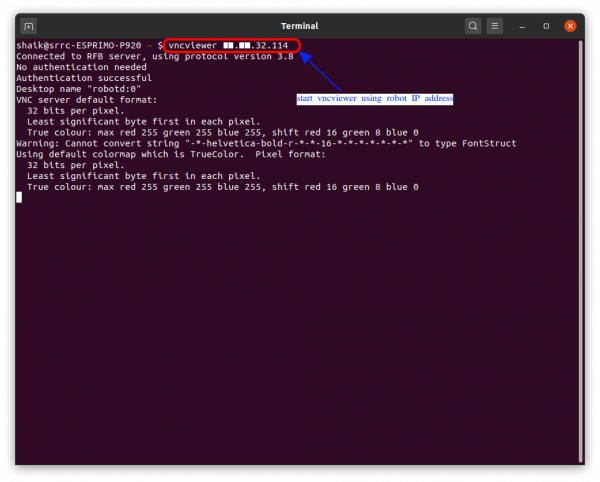
Step 6: Installation of the vncviewer in your PC for accessing the robot:
- sudo apt-get install xtightvncviewer
- of course, you can also use any other suitable tool
Start the Deployed System and Run the Robot
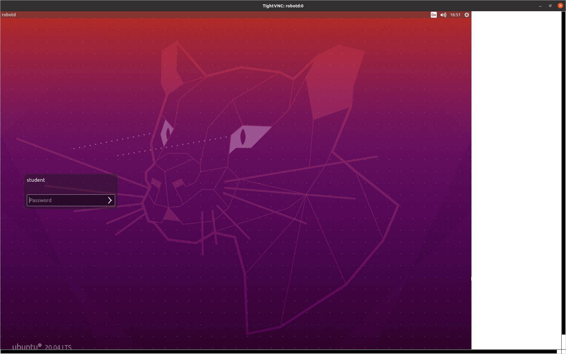
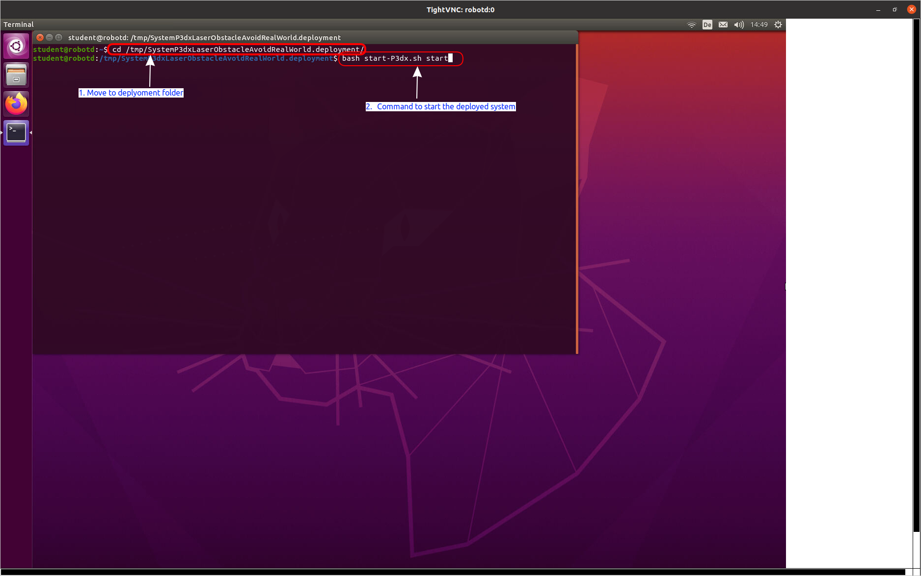
Step 7: Login to the robot with password student and then navigate to the specified deployment folder. The default folder is /tmp. In there you find a folder with the name of the system project. In this tutorial, we use SystemP3dxLaserObstacleAvoidRealWorld.
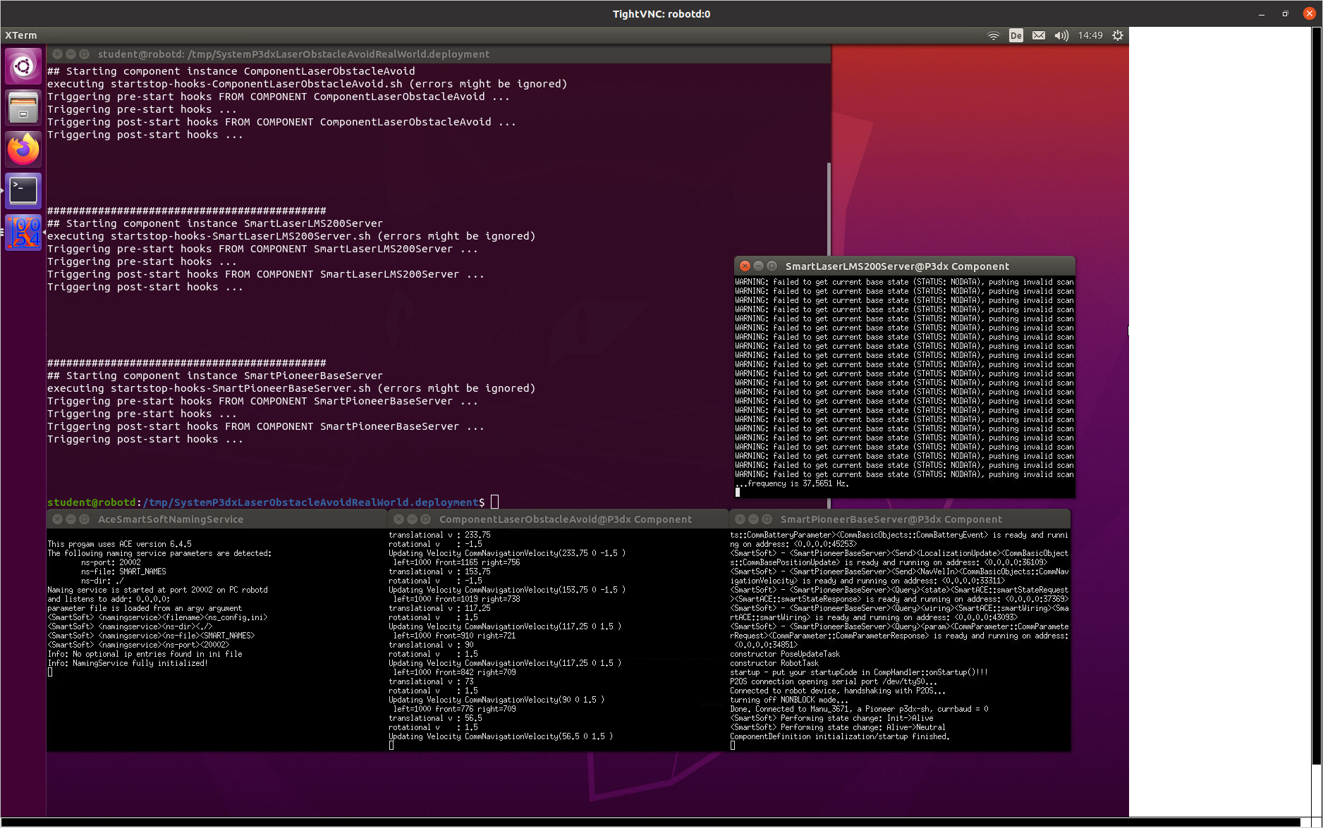
Step 8: Now you can start the system as shown below using the indicated shell script.
Stop the System
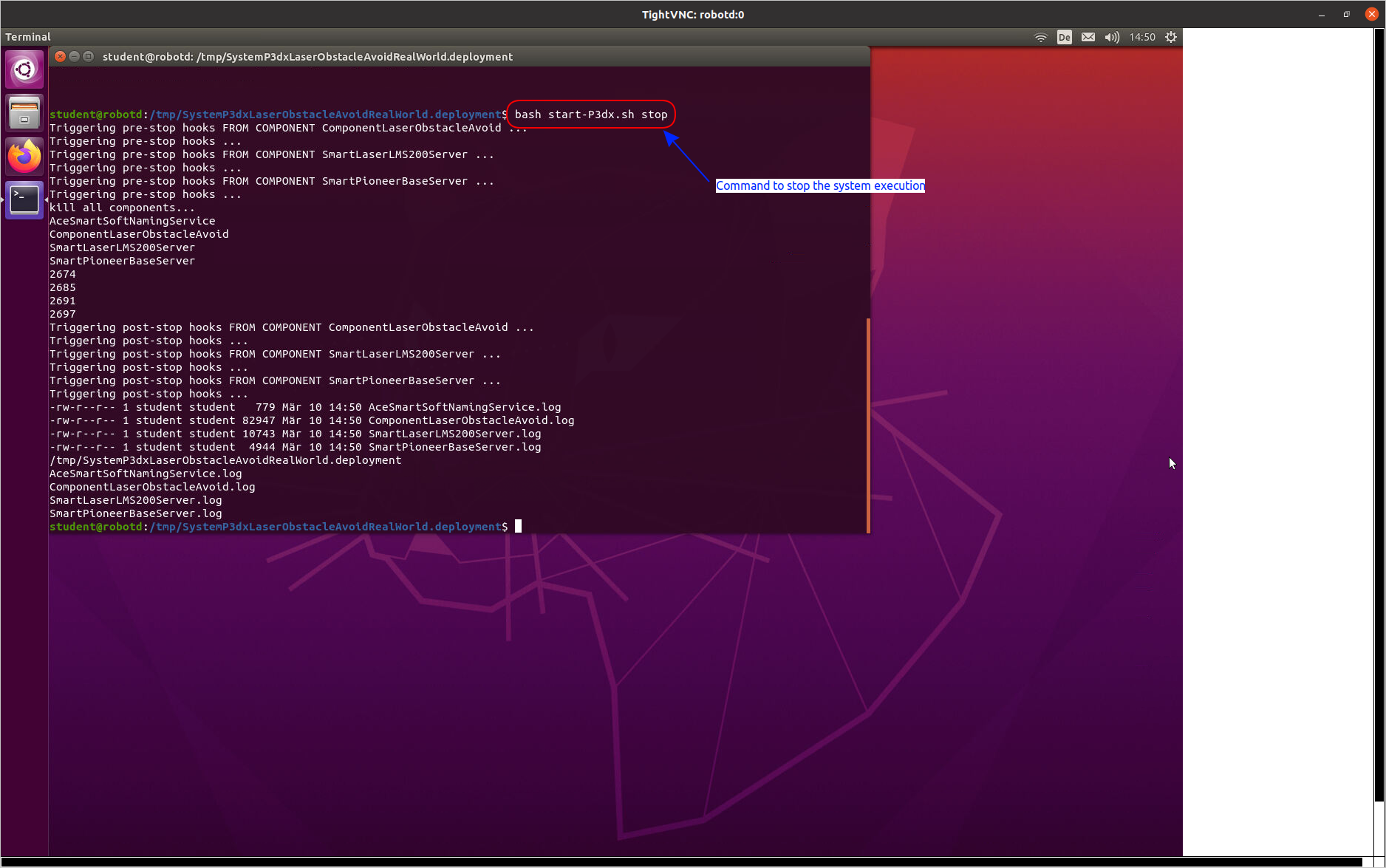
Step 9: You can use the same shell script to stop the system (use stop instead of start as argument)
What to do next?
Now you can proceed with tutorial Deploying the Flexible Navigation Stack in Real World.
