Table of Contents
Develop Your First System by Composing Software Components
Compose a system with a mobile robot, a laser ranger, a simple laser obstacle avoidance component and a simulator. We use a P3DX mobile robot and the Webots simulator.
This tutorial is also available as video tutorial.
Basic Information
| Level | Beginner |
|---|---|
| Role | System builder, but also other roles while browsing through the system's building blocks |
| Assumptions | Having completed the tutorial Develop Your First Software Component |
| System Requirements | Virtual Machine Image Installed, see ready-to-go virtual machine |
| You will Learn | See the different views related to systems How to compose a system from already available components How to configure a target platform How to configure a deployment (select a target platform, assign components to computers) How to deploy and start your system |
| Options | - SystemLaserObstacleAvoidP3dxWebotsSimulator - SystemLaserObstacleAvoidRobotinoWebotsSimulator |
Introduction
This tutorial guides you through the role of a system builder. From a set of already available software components, you select the ones you need for your robot system and compose them to a system. We illustrate that by a mobile robot that uses a simple obstacle avoidance algorithm to move around in a simulated environment. You know the system already from the tutorial Simple System: Laser Obstacle Avoid and the obstacle avoidance component from the tutorial Develop Your First Software Component.
The tutorial shows all the necessary steps. It starts with creating the system architecture model (selecting software components and composing them to a system). We then create a target platform model that describes a computing infrastructure. In the next step, we create a deployment model which maps all the elements of our system architecture (components) onto computers of a target platform. Finally, we show the deployment of the system and its execution.
System Architecture: Composition of Components
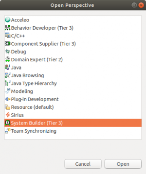
For working with system projects, we first need to open the System Builder (Tier 3) perspective. To do so, either directly click on the System Builder (Tier 3) tab located at the upper right in the Eclipse window (which will be visible after you opened this perspective for the first time). To open the persepctive initially, use the Open Perspective button and then select the System Builder (Tier 3) in the next popup window (see next screenshot). Please also read the new UI features HowTo for further information on the new perspectives.
We begin with modeling the system. The system model comprises instances of software components and also the connections between the components.
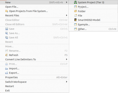
Step 1.a: The first step guides you through the process of creating a System Project. It will hold all our models. Start by clicking on File → New → System Project (Tier 3).
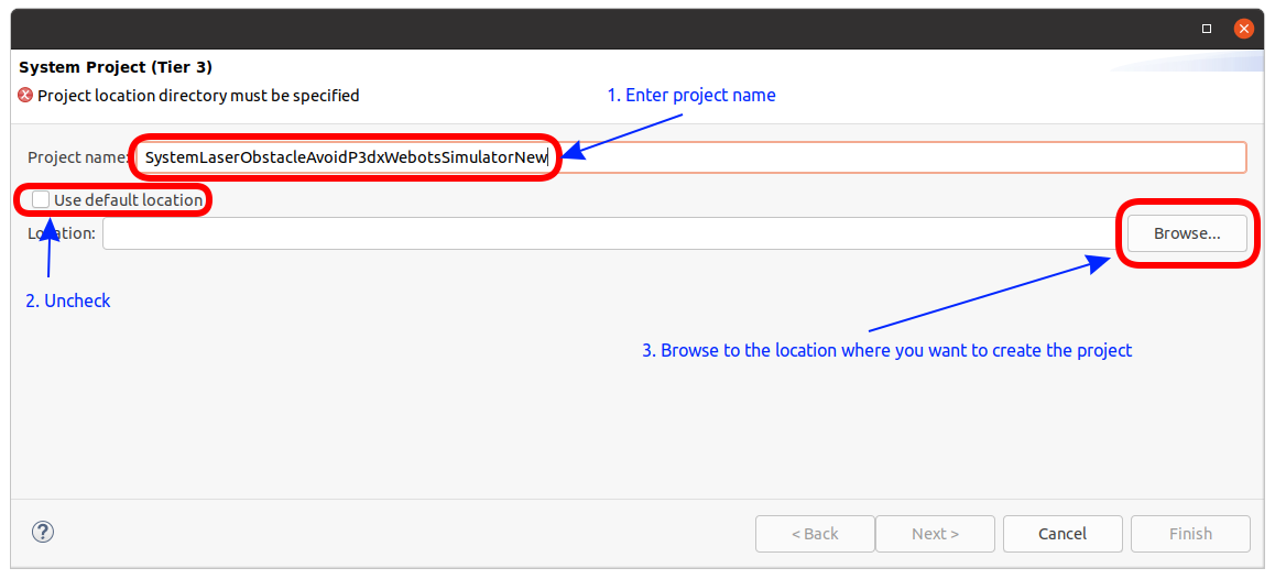
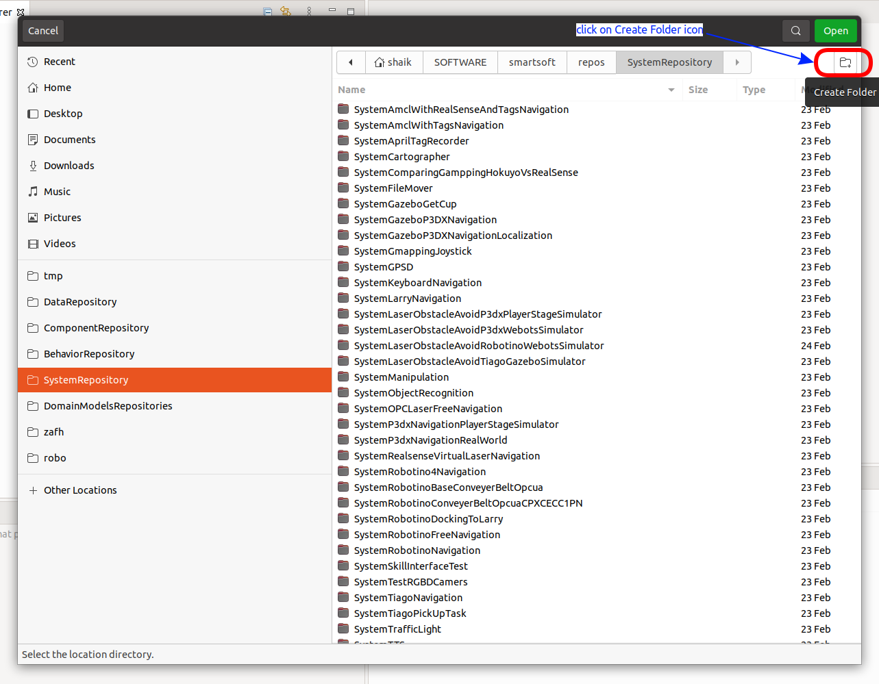
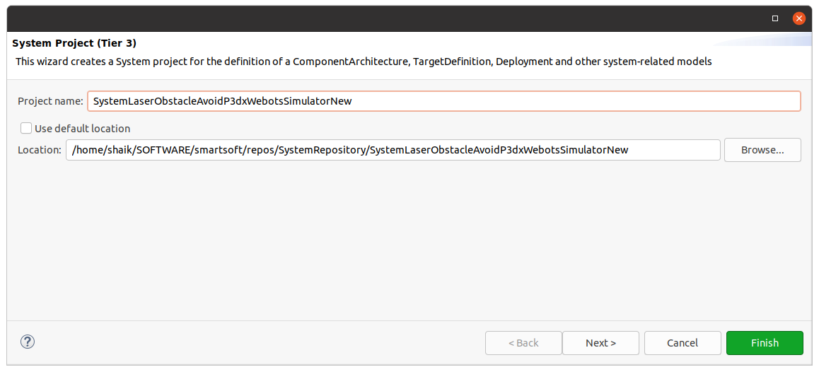
Enter the project name SystemLaserObstacleAvoidP3dxWebotsSimulatorNew. Uncheck Use default location and browse to the location $SMART_ROOT_ACE/repos/SystemRepository.
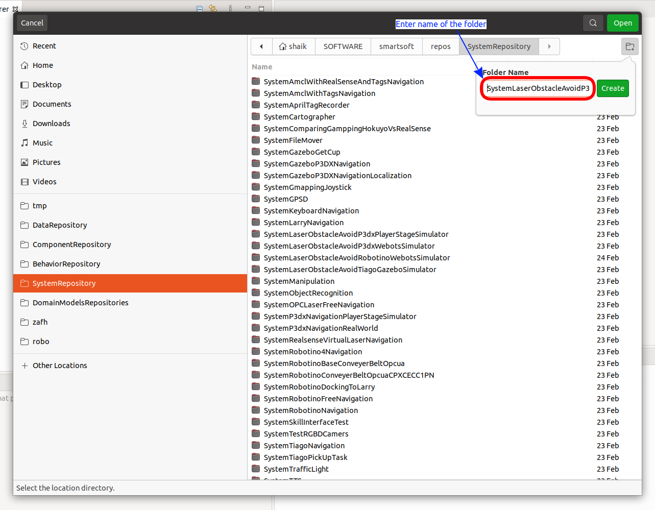
Now click Create Folder.
Enter SystemLaserObstacleAvoidP3dxWebotsSimulatorNew as the folder name and clickcreate.
Verify the project name and the location of the system project. If it is fine, press Finish.
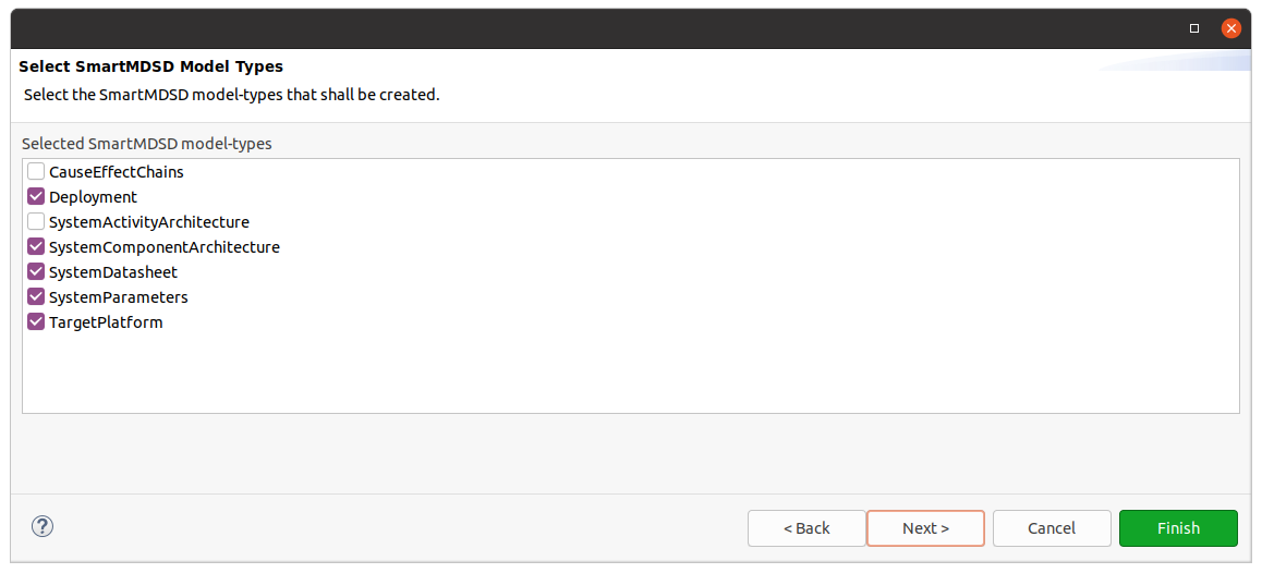
You now see the model types of the system project. Just keep the check boxes as is and click Next.
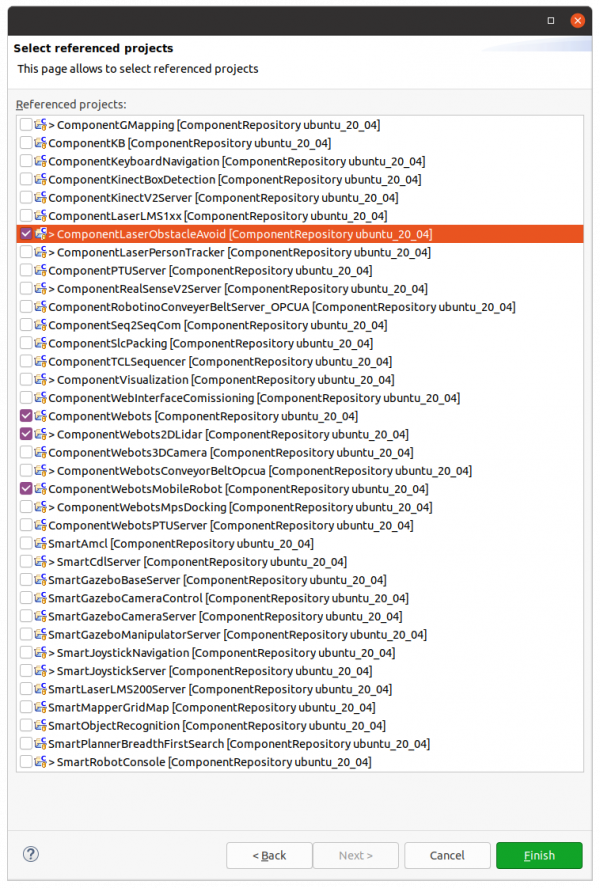
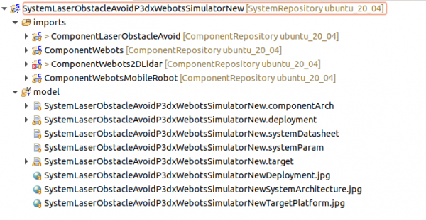
Now you see the set of components that are available in your workspace. Select the four components we need for our system as indicated in the figure below:
Now click Finish. The toolchain now creates the system project.
Step 1.b: We now navigate to the component architecture file of our system project.
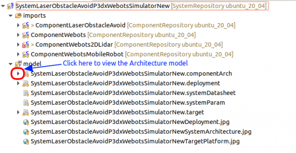
To open the component architecture file, click on the triangle next to the componentArch file:
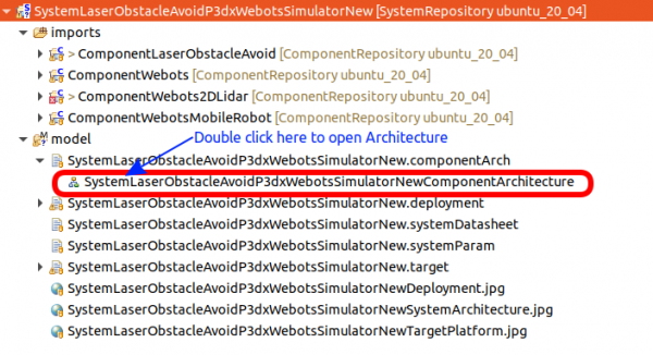
Now double-click on the ComponentArchitecture:
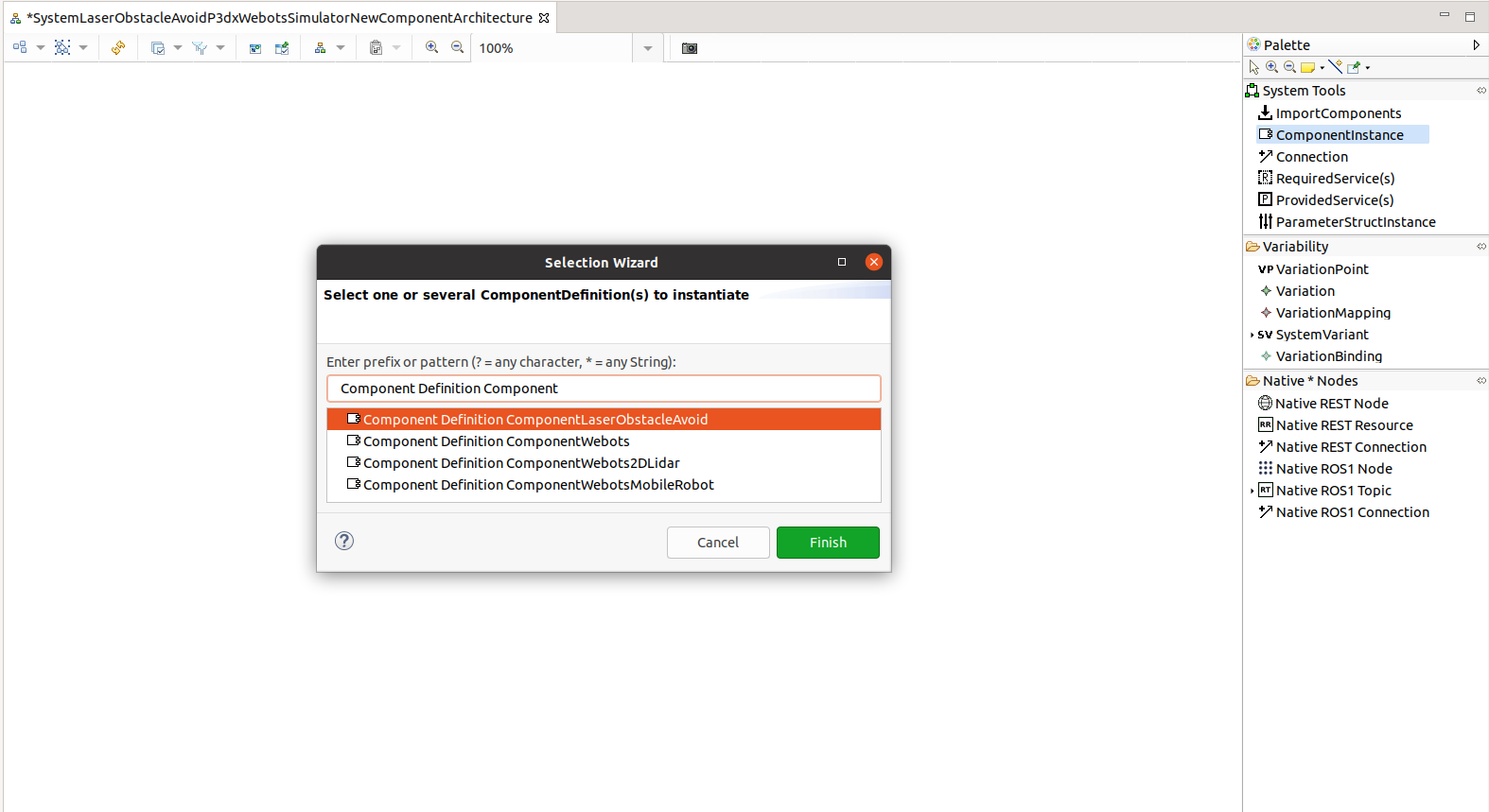
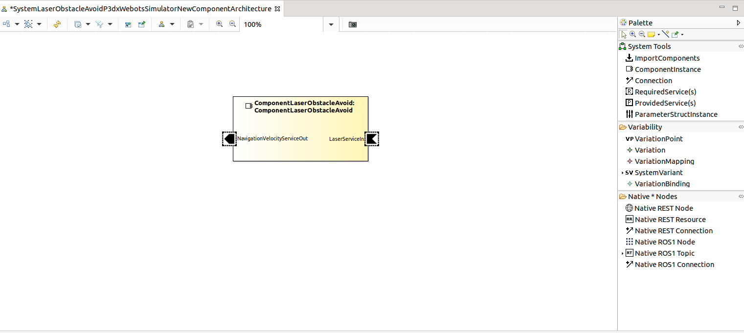
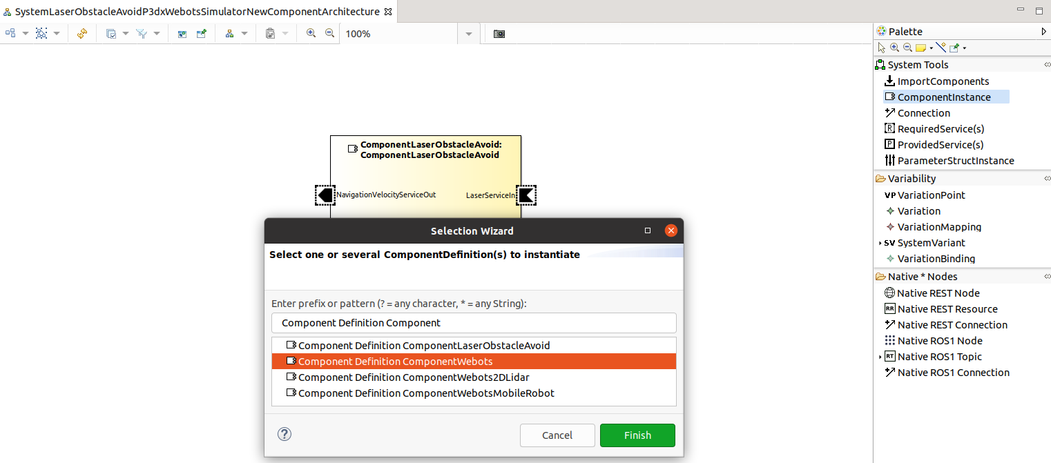
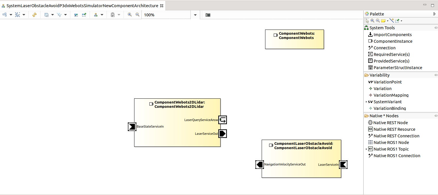
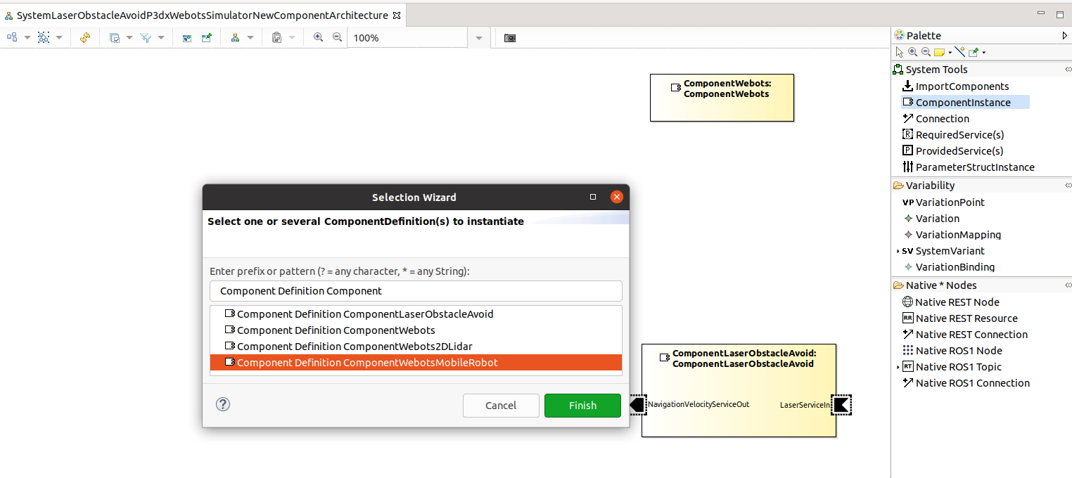
Step 1.c: guides you through creating the instances of the components. Drag the ComponentInstance from the System Tools into the empty system architecture file. A selection wizard opens. Select the Component Definition ComponentLaserObstacleAvoid and click Finish.
Now the ComponentLaserObstacleAvoid instance got added. You can rearrange the ports and the port names to get the following result:
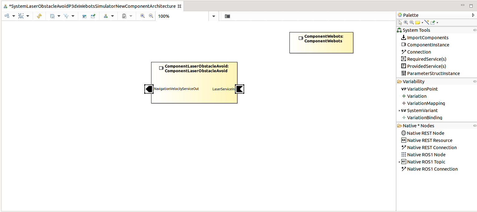
Drag the ComponentInstance from the System Tools into the empty system architecture file. A selection wizard opens. Select the Component Definition ComponentWebots and click Finish.
Now the ComponentWebots instance got added. You can rearrange the ports and the port names to get the following result:
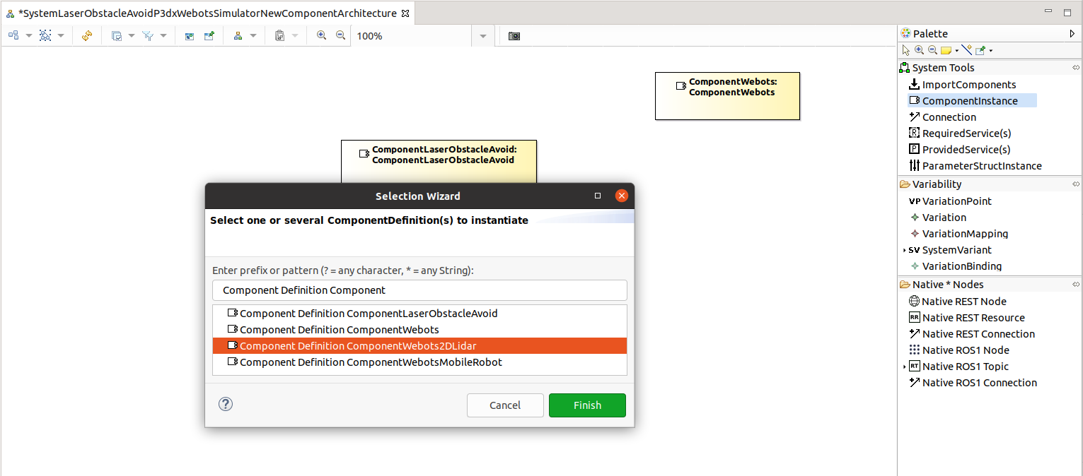
Drag the ComponentInstance from the System Tools into the empty system architecture file. A selection wizard opens. Select the Component Definition ComponentWebots2DLidar and click Finish.
Now the ComponentWebots2DLidar instance got added. You can rearrange the ports and the port names to get the following result:
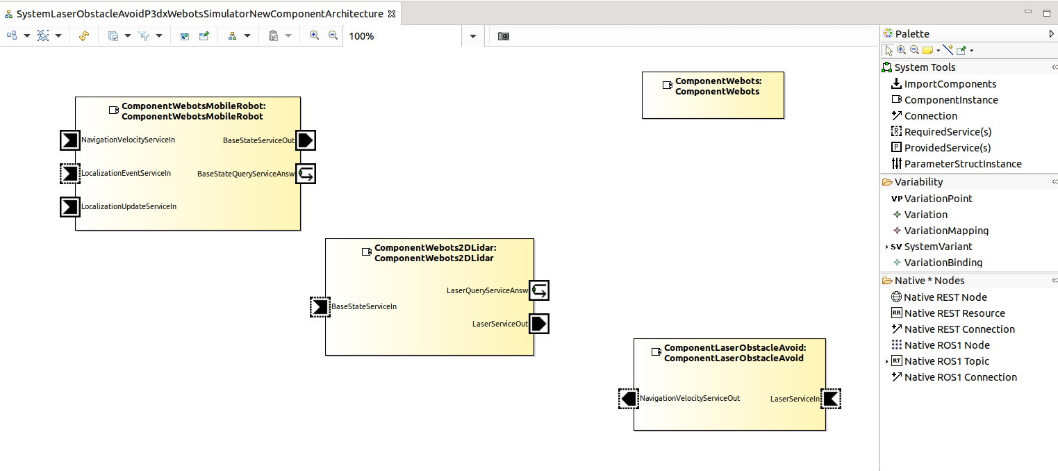
Drag the ComponentInstance from the System Tools into the empty system architecture file. A selection wizard opens. Select the Component Definition ComponentWebotsMobileRobot and click Finish.
Now the ComponentWebots2MobileRobot instance got added. You can rearrange the ports and the port names to get the following result:
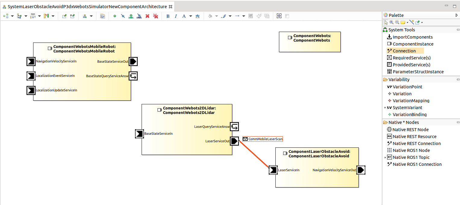
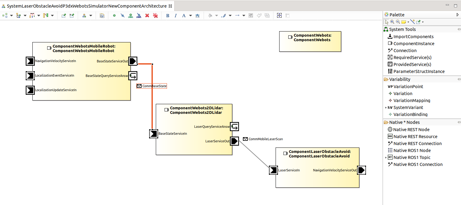
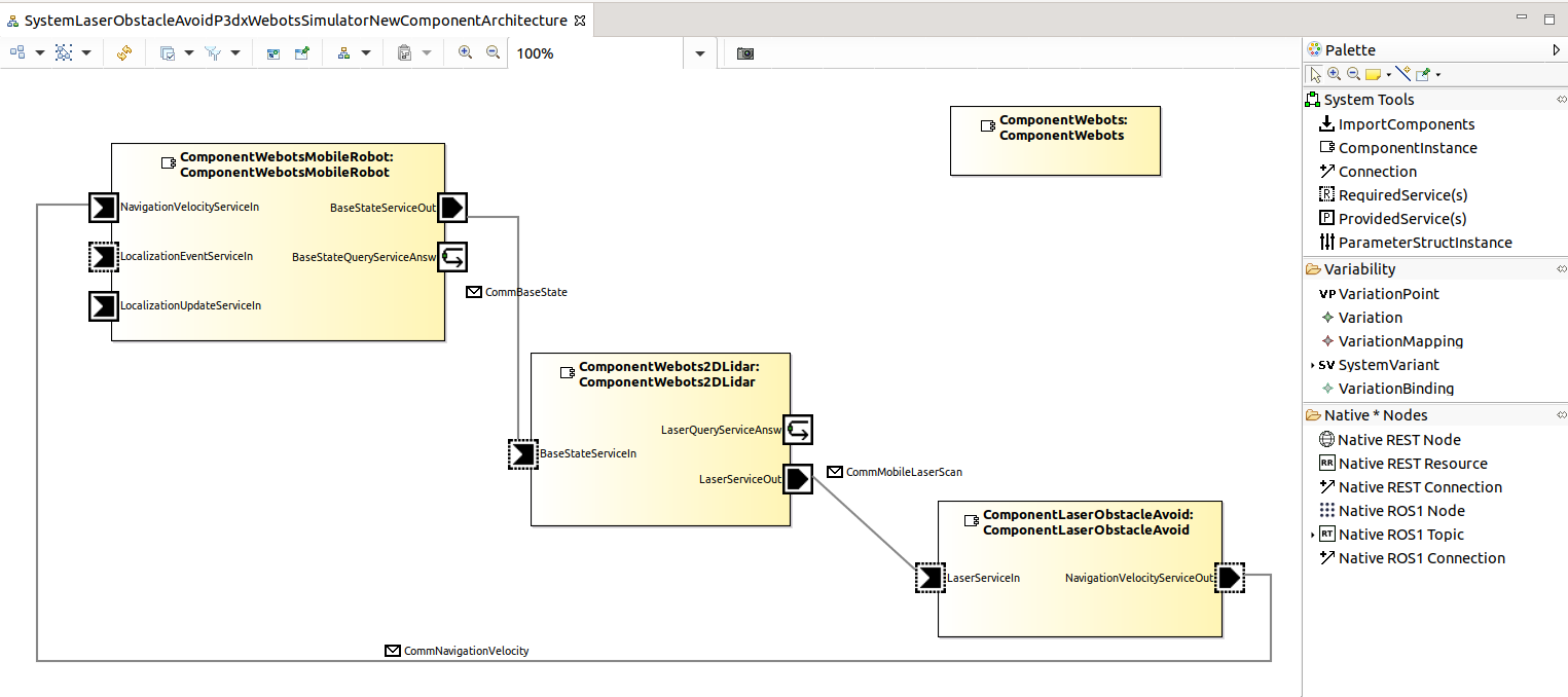
Step 1.d: We now connect the ports of the components. Drag the Connection from the System Tools to the LaserServiceIn port of the ComponentLaserObstacleAvoid and click and continue to drag to the LaserServiceOut port of the ComponentWebots3DLIdar.
Drag the Connection from the System Tools to the BaseStateServiceIn port of the ComponentWebots2DLidar and click and continue to drag to the BaseStateServiceOut port of the ComponentWebotsMobileRobot.
Drag the Connection from the System Tools to the NavigationVelocityServiceOut port of the ComponentLaserObstacleAvoid and click and continue to drag to the NavigationVelocityServiceIn port of the ComponentWebotsMobileRobot.
Target Platform Model
We now modeled the system architecture (added component instances and the connections of their ports). We now model the target platform which we need later on when we assign software components to processing units.
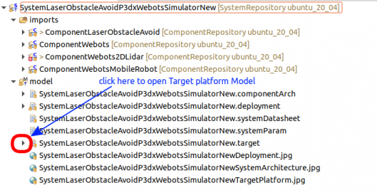
Step 2.a: Open the target platform model by clicking on the triangle icon as shown below:
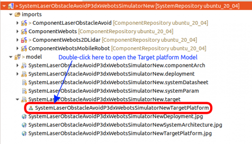
Now double click on the target platform model:
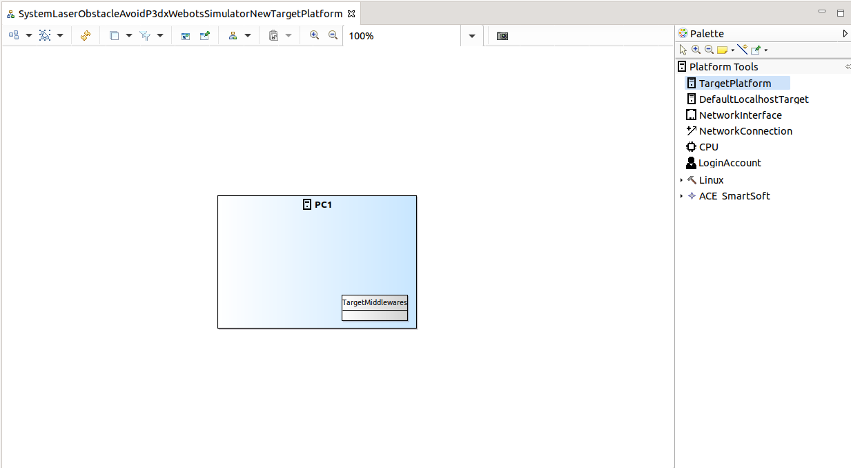
Step 2.b: Drag the TargetPlatform form the Platform Tools to the empty Target Platform Model.
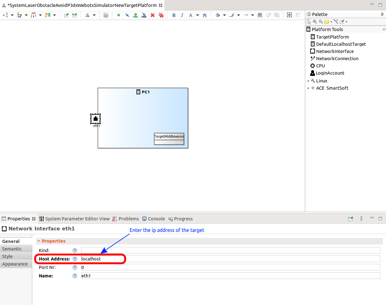
Step 2.c: Now add the network interface by dragging the NetworkInterface from the Platform Tools onto the PC 1 box. As your PC is used as target for running the robot system we build right now, we configure the host address as localhost.
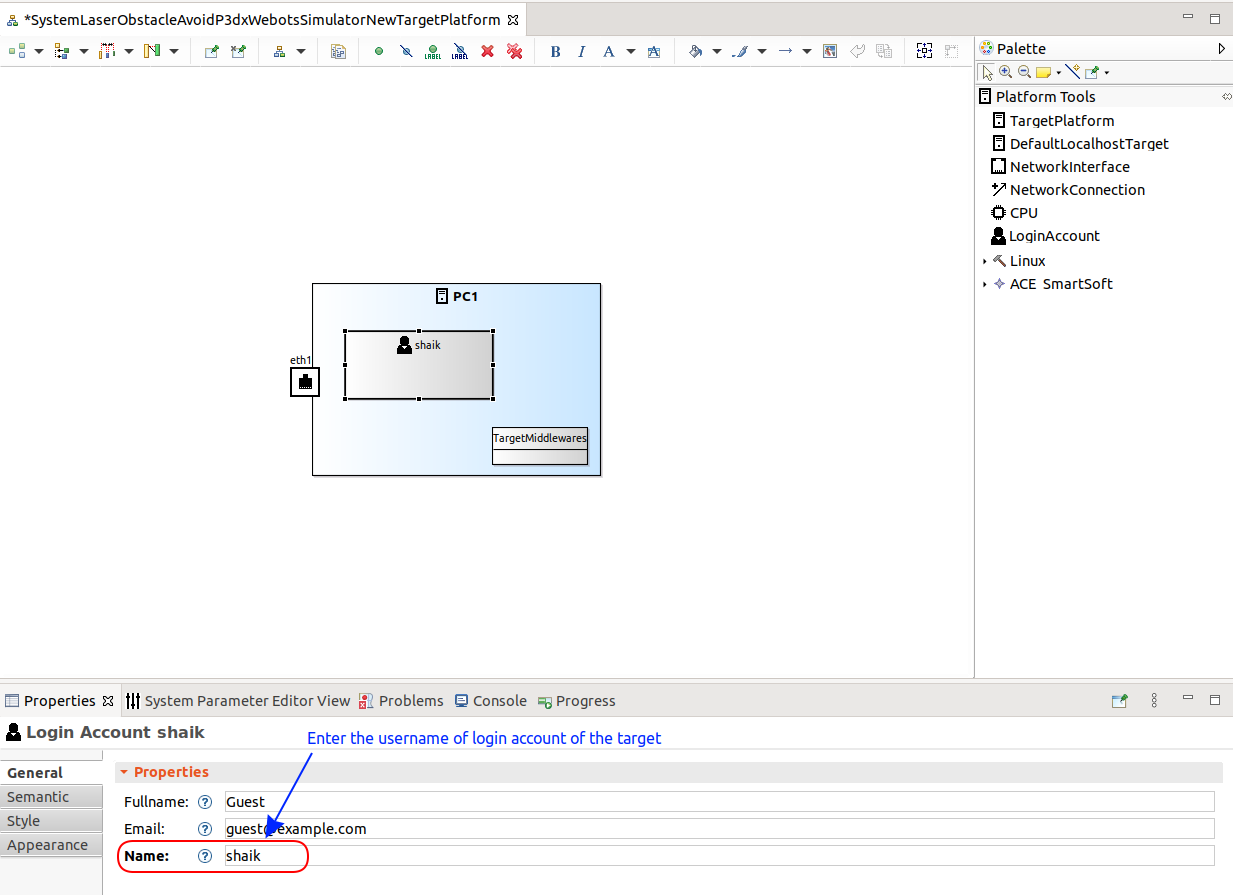
Step 2.d: We now have to add the username of a login account on the target system. This is used later on in the deployment step (when you use the virtual appliance, you can use the smartsoft account).
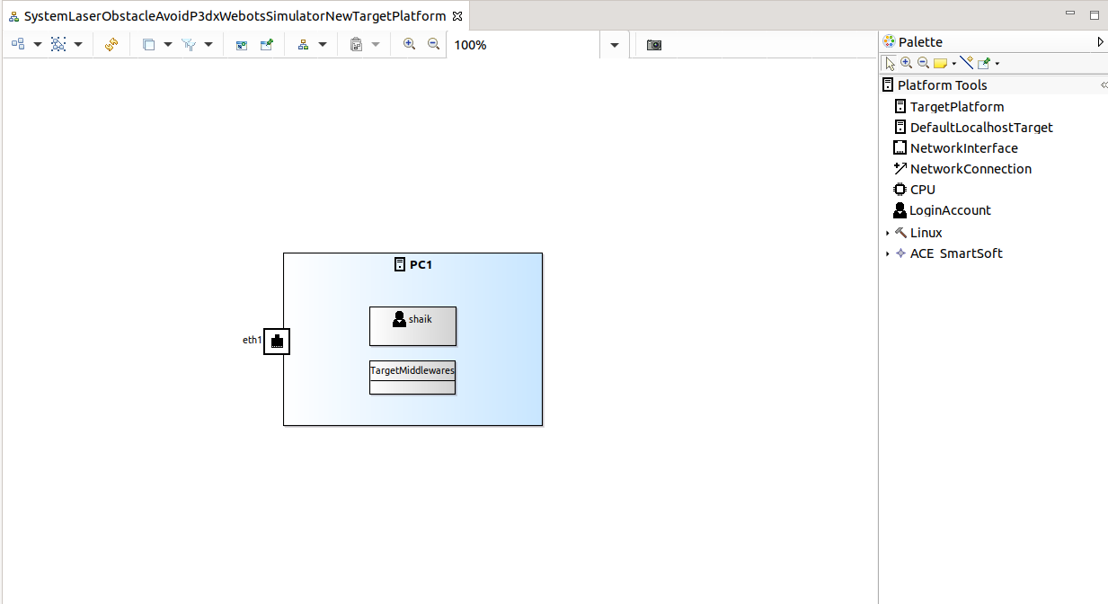
Now we completed the target platform model. You can rearrange the model elements to look as in the following picture:
Deployment Model
Now your system is ready to model the deployment of the components. The deployment model defines which components are going to be deployed / transferred to which target platform(s) / processing unit(s) / computer(s). In this educational tutorial, we deploy to your local system. Please see subsequent tutorials to learn how to deploy your system to real robots (and other remote systems). It is even possible to deploy to multiple systems.
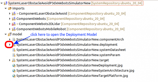
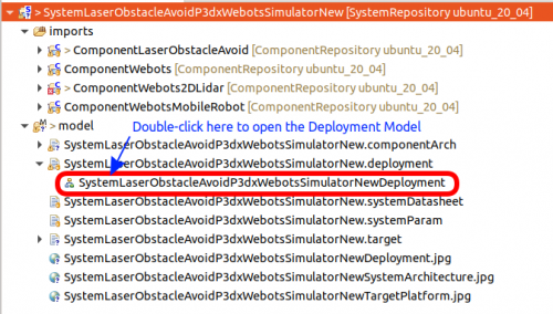
Step 3.a: Open the deployment model:
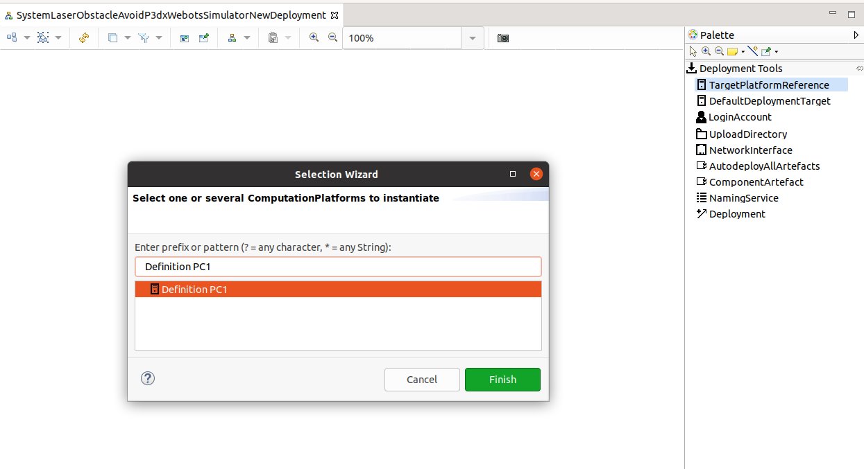
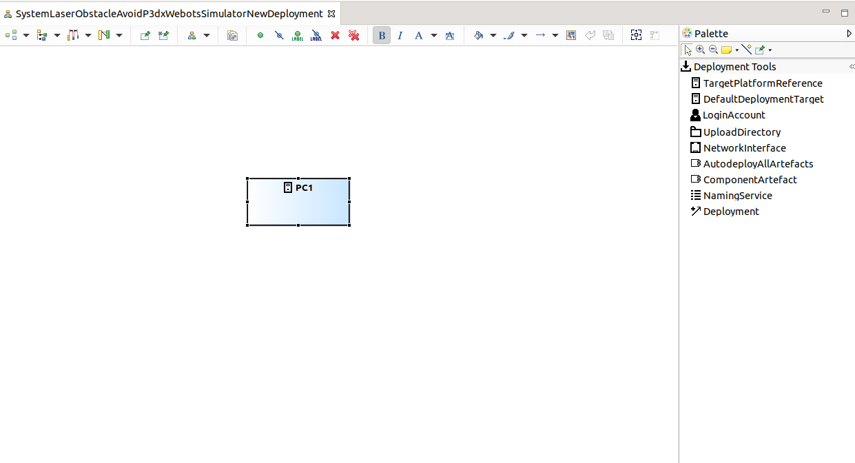
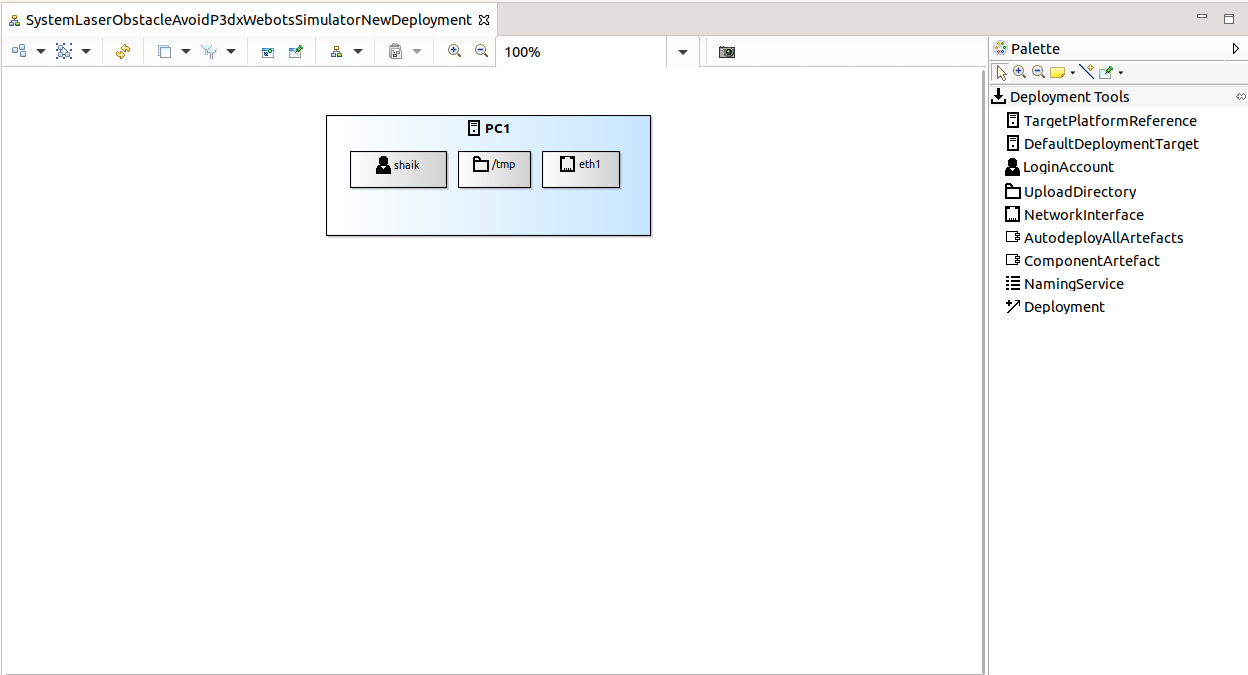
Step 3.b: Add the TargetPlatformReference by dragging. A selection wizard opens. Select the target platform (in this case, you see the target platform as configured in the Target Platform Model steps) and click Finish.
It now looks as follows:
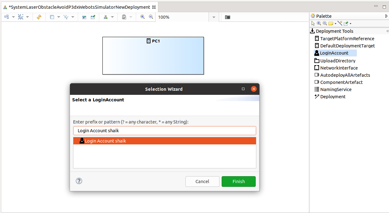
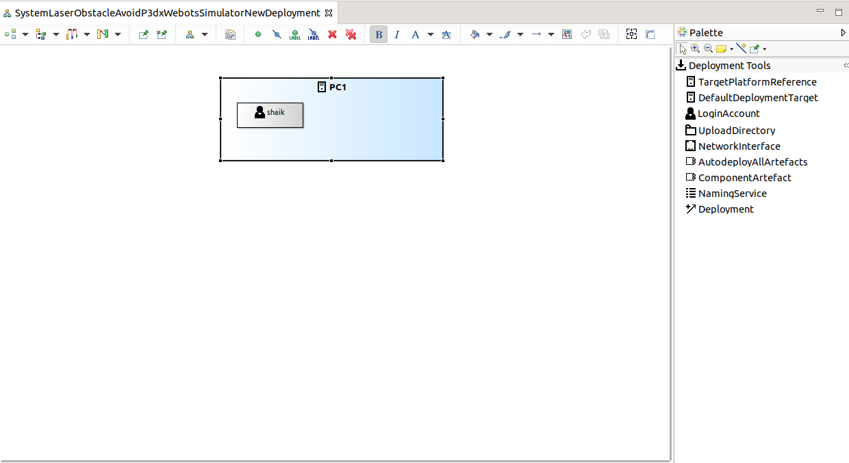
Step 3.c: Now add the LoginAccount by dragging it from the Deployment Tools. A selection wizard opens. Select the login account (in this case, you see the login account as configured in the Target Platform Model steps) and click Finish.
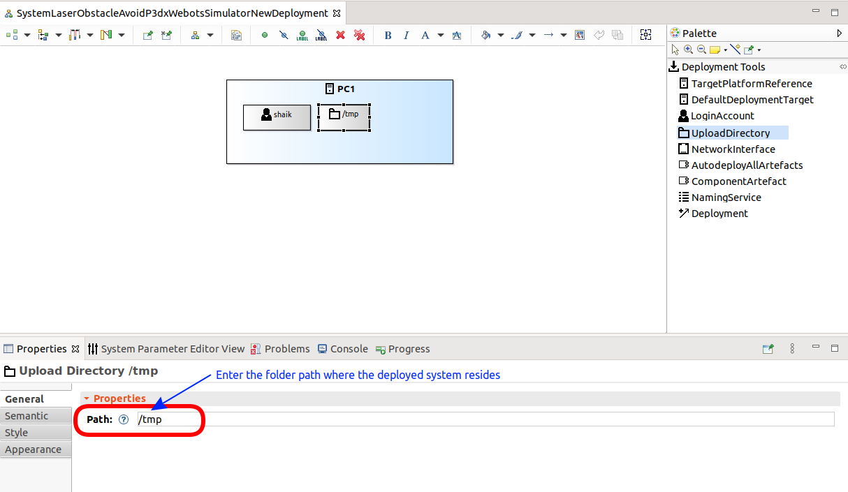
Step 3.d: Add the UploadDirectory by dragging. Keep the /tmp default path (in case you want the system to reside in a different place, then you can specify this here to your needs):
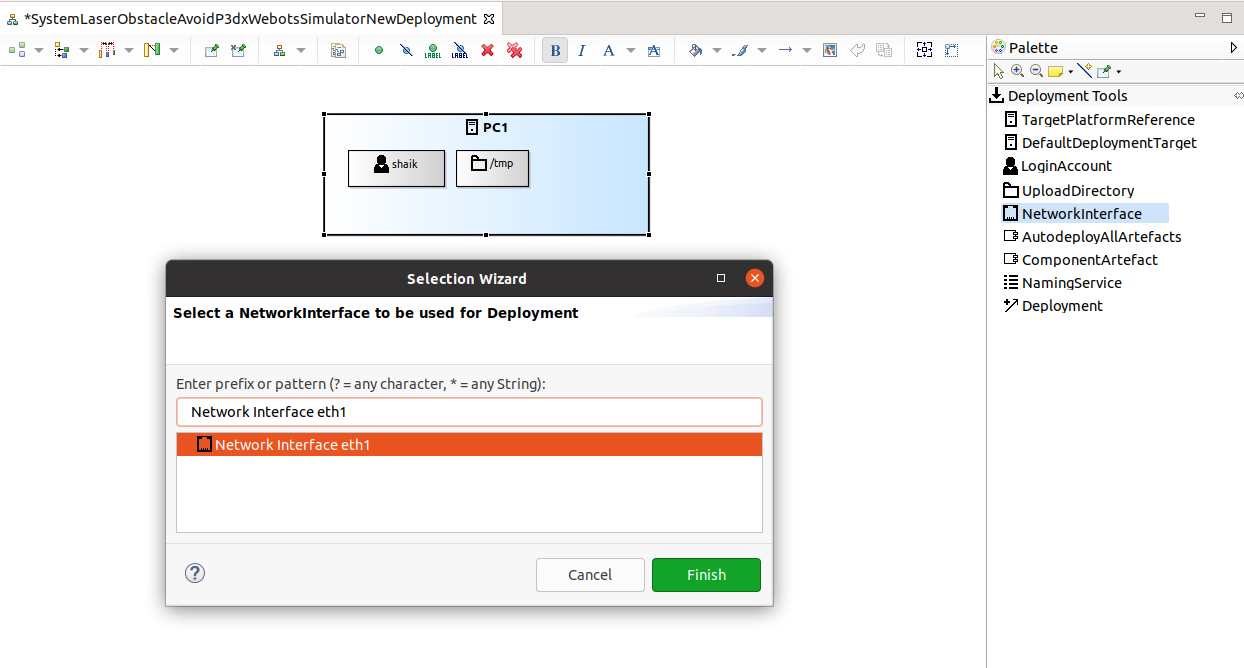
Step 3.e: Add the NetworkInterface by dragging:
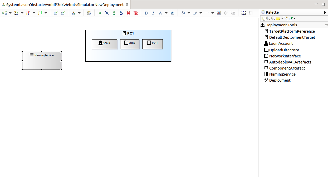
Step 3.f: Add an instance of the NamingService by dragging it from the Deployment Tools:
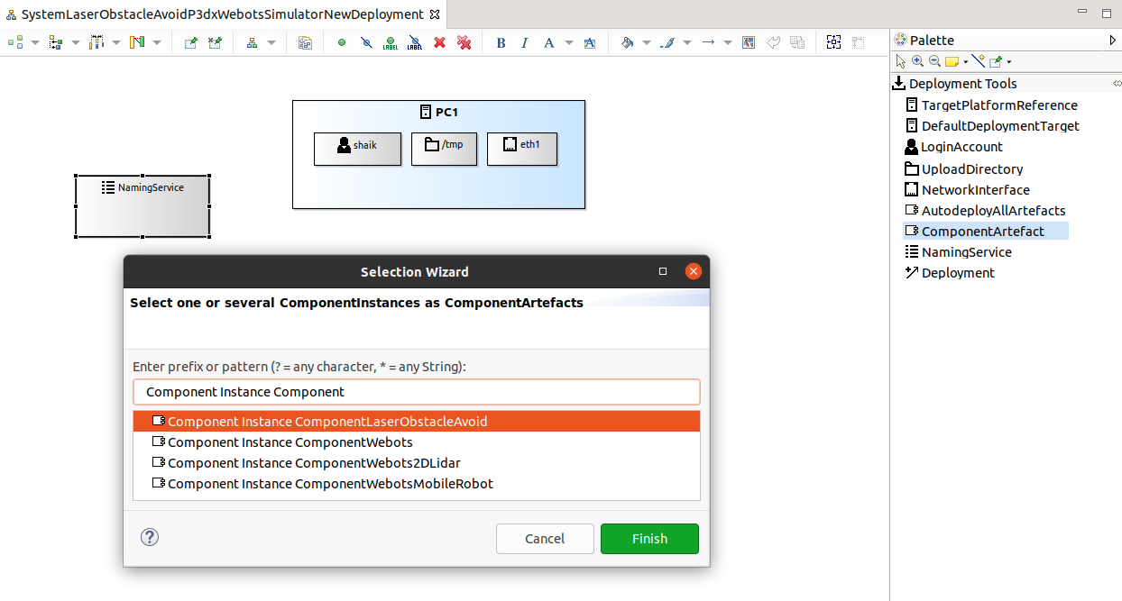
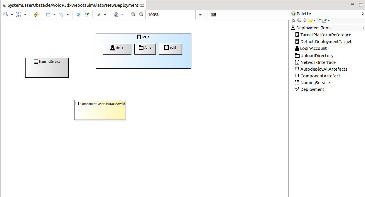
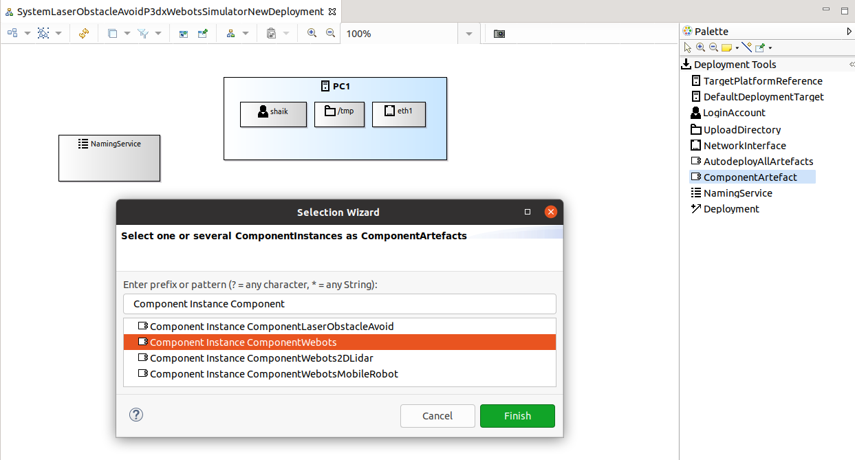
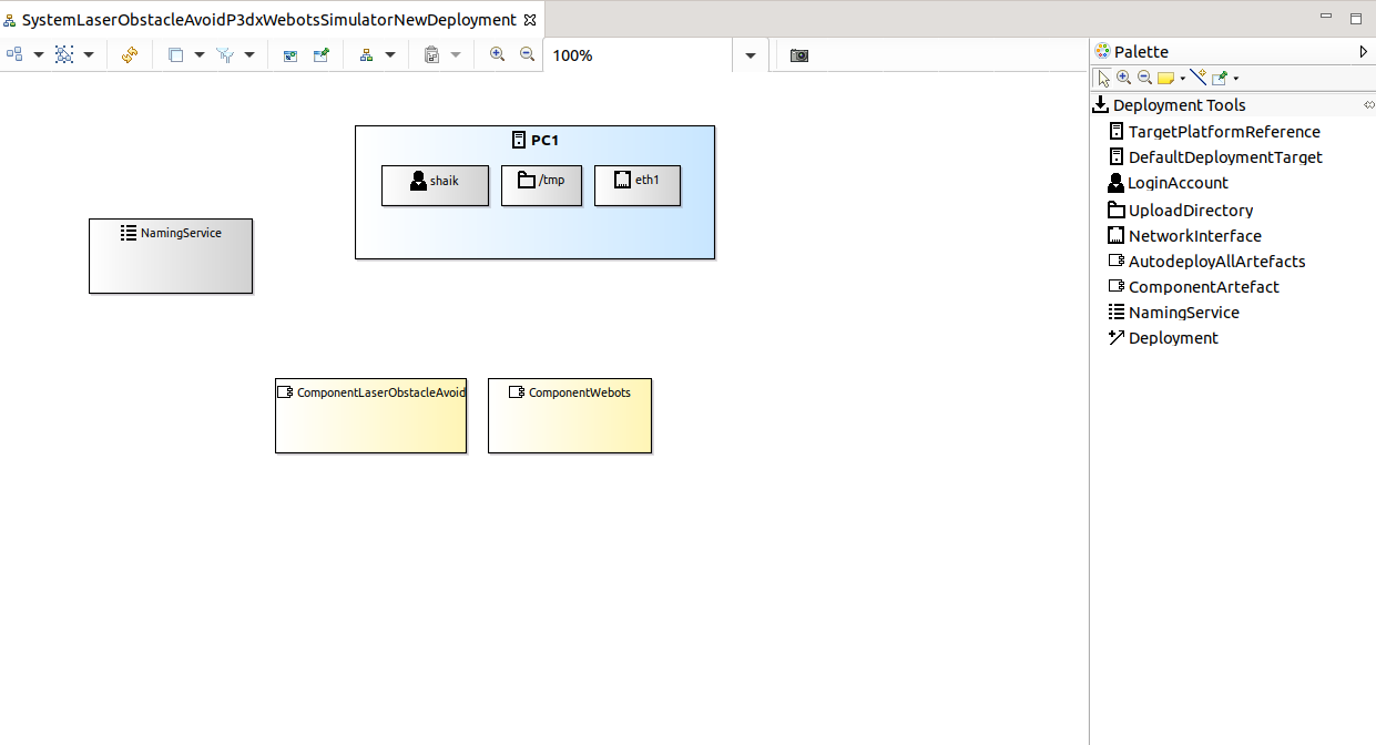
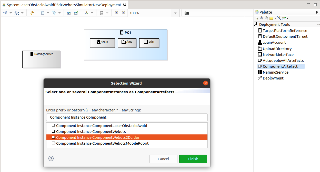
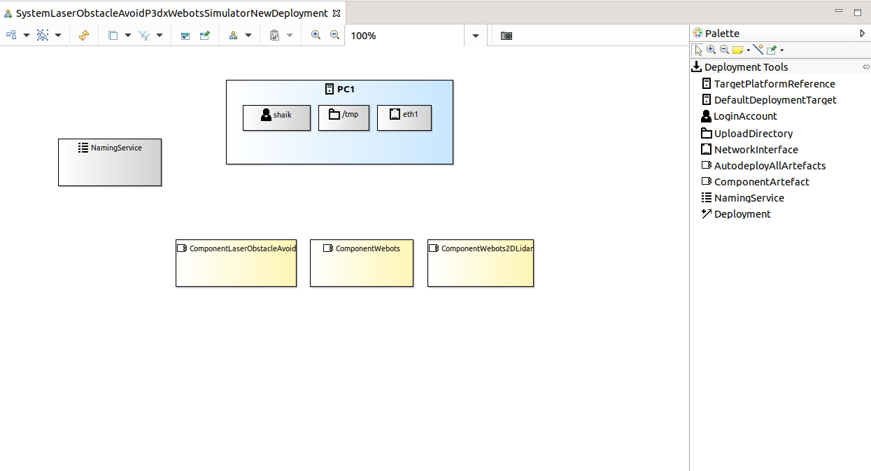
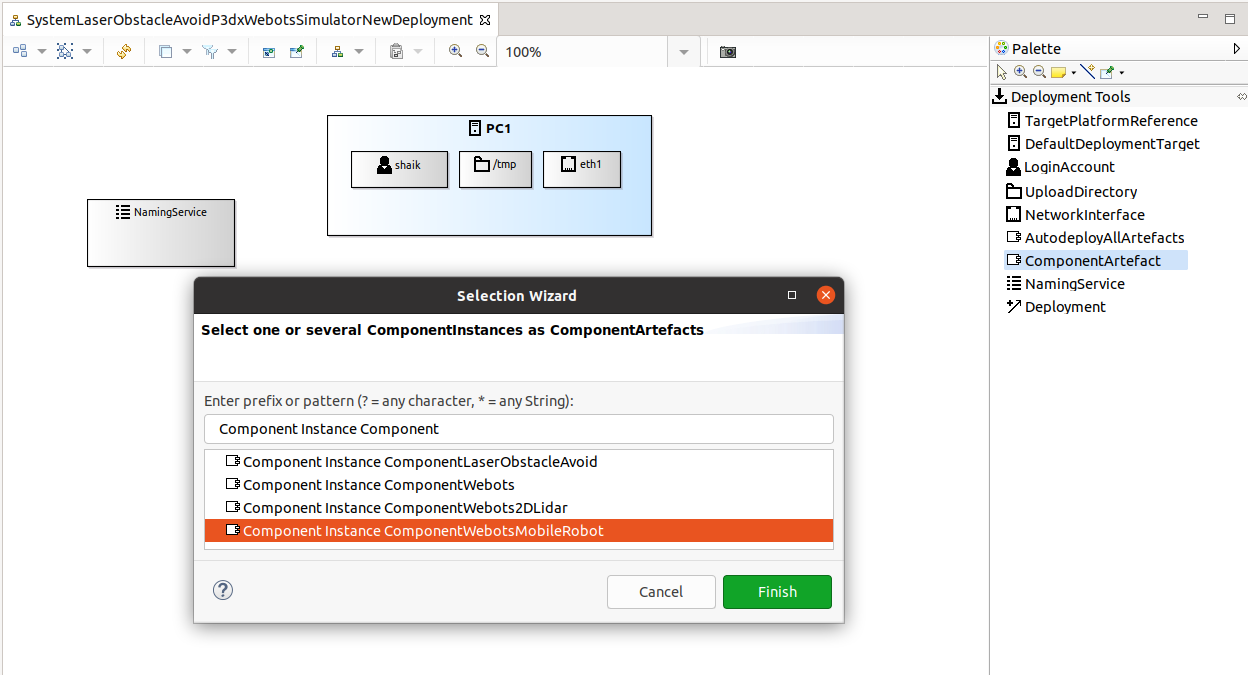
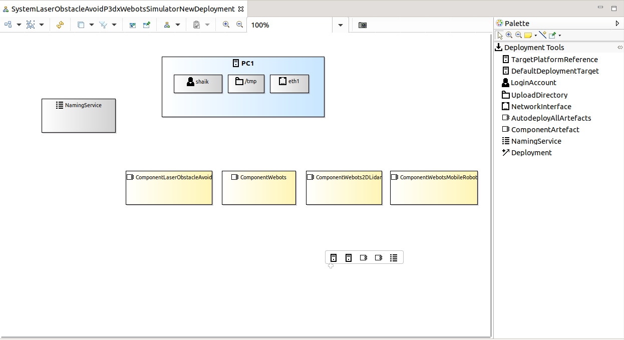
Step 3.g: We now add the ComponentArtefacts by dragging from the Deployment Tools. This opens a wizard where you select a component instance. You need to repeat that for all the components used in our system.
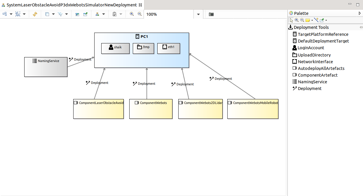
Step 3.h: We now need to assign the component instances to the target platform. This specifies where the component instance gets deployed and executed. You do the connections by dragging the Deployment from the Deployment Tools.
Now the last model of system modeling is complete. The system is ready for deployment.
System Parameters
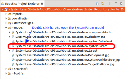
Step 4.a: Open the system parameter modeler.
Now you see the empty system parameter file:
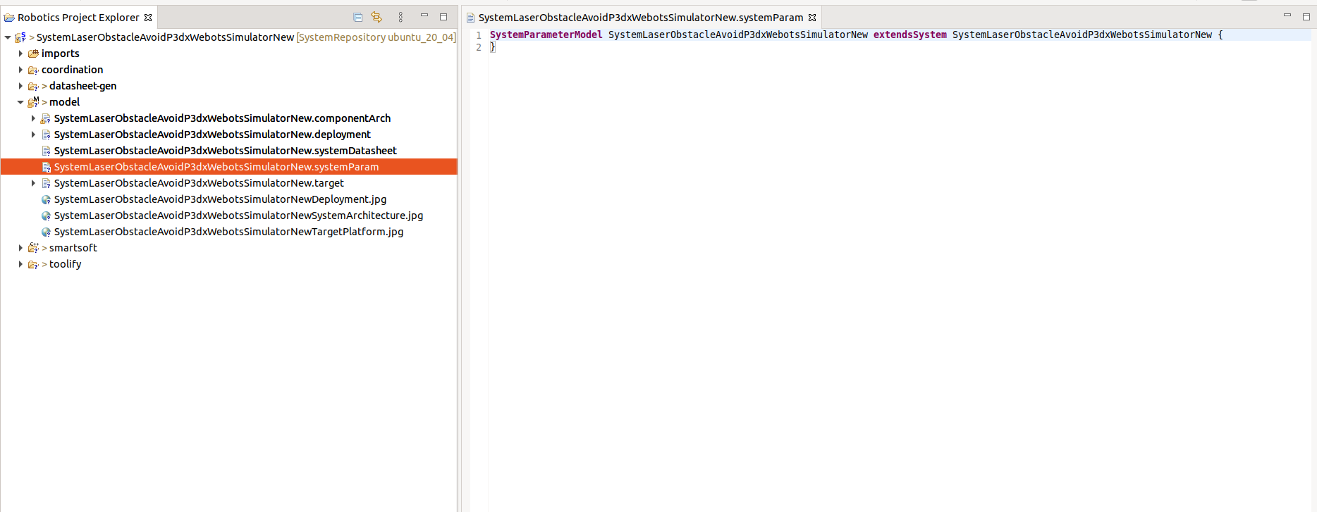
Step 4.b: Copy & Paste the following content into your system parameter file:
- SystemLaserObstacleAvoidP3dxWebotsSimulatorNew.systemParam
SystemParameterModel SystemLaserObstacleAvoidP3dxWebotsSimulatorNew extendsSystem SystemLaserObstacleAvoidP3dxWebotsSimulatorNew {

	ComponentParameterInstance ComponentWebots refinesParamStruct ComponentWebots {
		ParameterRefinement General {
			/** Webots world which contains the simulated environment, robot and lidar*/
			WorldPath = "$SMART_ROOT_ACE/repos/DataRepository/webots/worlds/P3dxHospital.wbt"
		}
	}

	ComponentParameterInstance ComponentWebotsMobileRobot refinesParamStruct ComponentWebotsMobileRobotParams {
		ParameterRefinement Webots {
			/**Robot name in the Webots world */
			robotName = "Pioneer 3-DX"
			/** names of motors of wheels */
			motorName = ["left wheel", "right wheel"]
			/** radius of wheels in m */
			radius = [0.0975, 0.0975]
			/** distance of a wheel to the turning point (center) of the robot [m]*/
			distanceToRobotCentre = [-0.165, 0.165]
			/** the heading of the wheels [??], for differential drives set these to 0 */
			heading = [0, 0]
			/** maximum acceleration for front[m/s] sideways[m/s], rotation[radians/s] movements*/
			maxAcceleration = [1.0, 0.0, 15.0]
		}
	}

	ComponentParameterInstance ComponentWebots2DLidar refinesParamStruct ComponentWebots2DLidarParams{
		ParameterRefinement webots {
		/** Name of the lidar in the Webots world*/
			robotName = "LidarPioneer"
		}
		ParameterRefinement scanner {
			verbose = true
			on_turret = false
			/** position of the lidar relative to the robot in [mm] */
			x = 70
			y = 0
			z = 0
			/** orientation of the lidar relative to the robot in [radians] */
			azimuth = 0
			elevation = 0
			roll = 0
			/** lidar minimum range in [mm]*/
			min_range = 10
			/** lidar maximum range in [mm]*/
			max_range = 80000
			/** lidar field of view in [degrees]*/
			opening_angle = 180
			/** lidar resolution i.e the angle between two lidar rays in [degrees]*/
			resolution = 1
		}
	}
}
Deployment and Execution
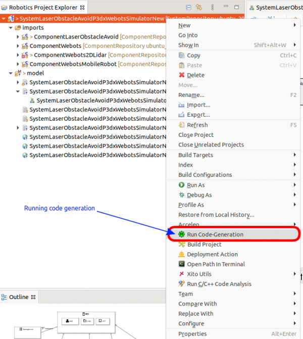
Step 5.a: Right click on the project → Run Code-Generation. This generates startup scripts and configuration files (used by the components during their initialization). It also generates the data folders where the components find required data (e.g. maps of the environment as specified by the system builder).
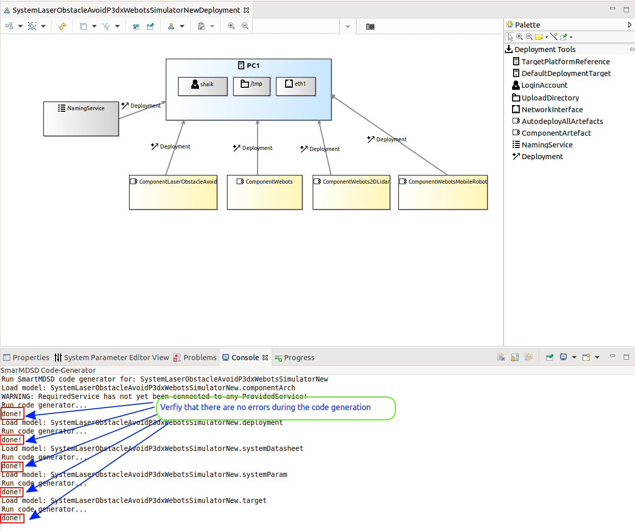
Verify that there are no errors during the code generation by looking at the Console terminal:
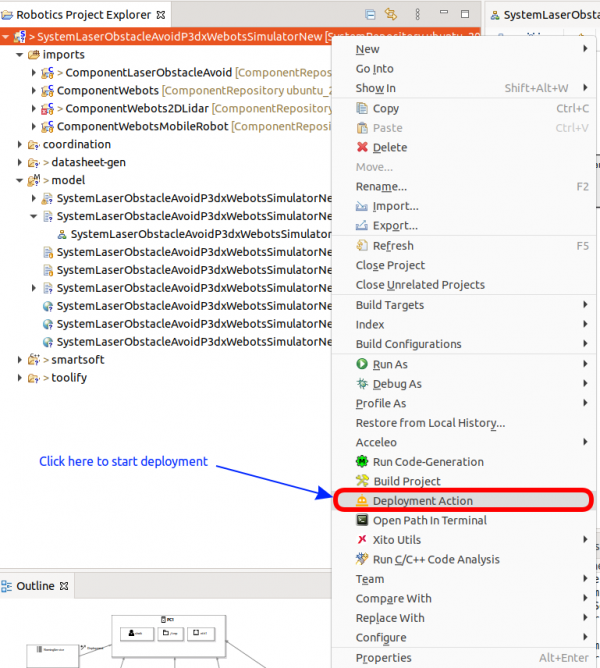
Step 5.b: We now deploy the system by clicking the Deployment Action from the right-click menu of the project:
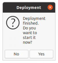
It depends on your configuration whether you are being asked for credentials of the configured login account. Finally, you see the following pop-up window which tells you that the deployment was successful:
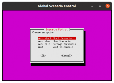
Step 5.c (first option): You can now start your system by clicking Yes. A terminal window will open and show the scenario control menu. Choose menu-start to start the scenario. Further terminals open automatically (one for each component and one additional window for the naming service). Note that they may not be visible initially in case they overlap. Choose menu-stop to stop the scenario.
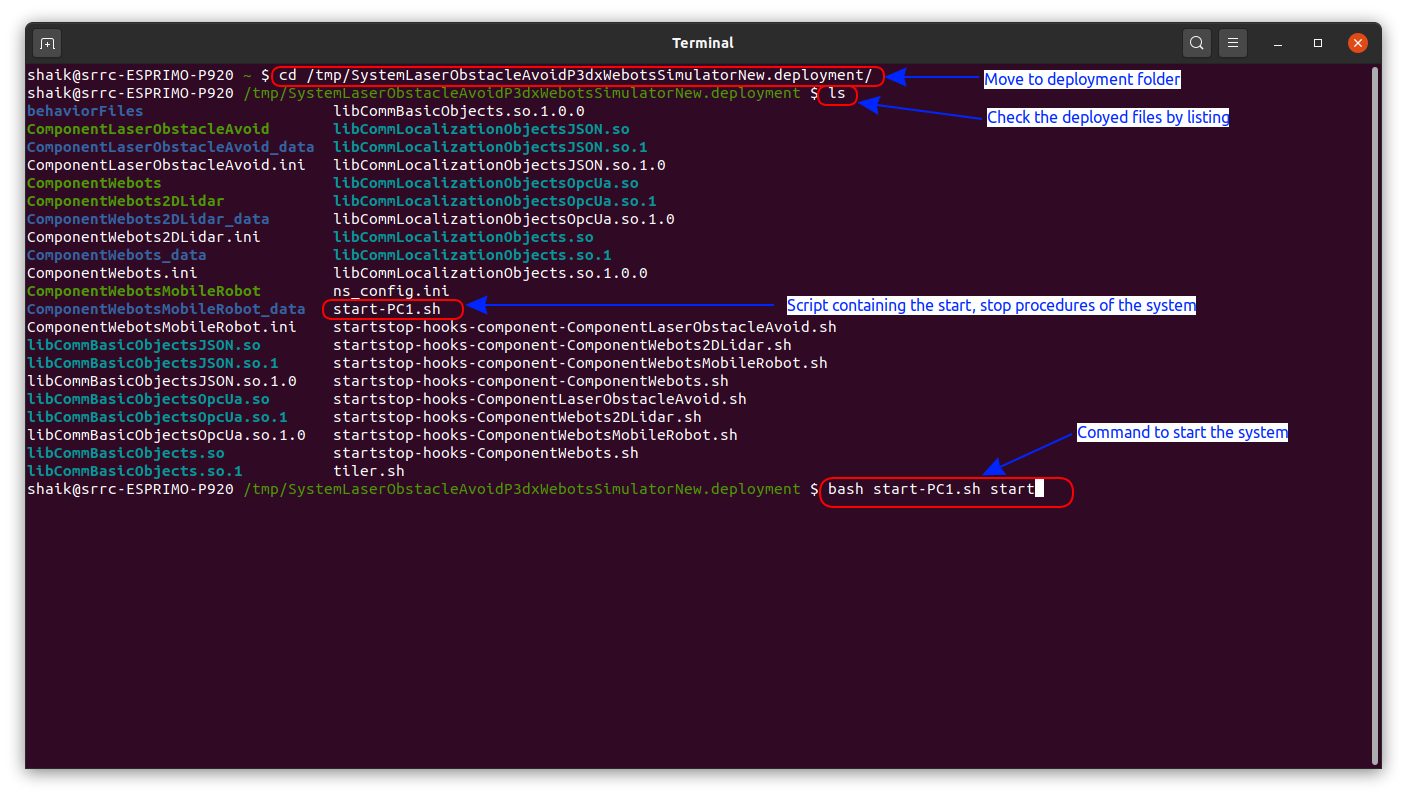
Step 5.c (second option): If you press No, you can start the system later from the terminal. First open a new terminal, then change to the indicated folder (which contains the deployed files including the scripts to start / stop the execution of the system). Start the indicated shell script as shown below.
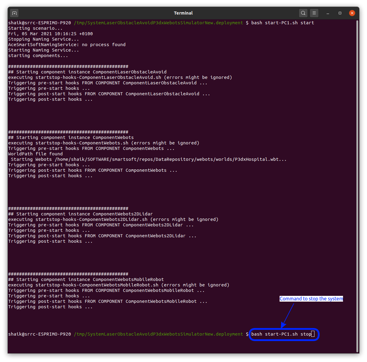
You can use the same shell script to stop the system (use stop instead of start as argument):
What to do next?
Please proceed with the tutorial Deploying the Flexible Navigation Stack in Real World to learn how to deploy a system onto a physical robot.


