Table of Contents
Develop Your First Domain Model
This tutorial will guide you through modeling of your first communication object and service definition. Both are the basis for every component do develop.
Basic Information
| Level | Beginner |
|---|---|
| Role | Component Supplier, but also other roles while browsing through the system's building blocks |
| Assumptions | Basic understanding of communication patterns is a plus |
| System Requirements | Virtual Machine Image Installed, see ready-to-go virtual machine |
| You will learn | How to model a communication object How to choose model a service definition |
Introduction
To model a software component (Tutorial), you have to select service definitions when creating a component port. In this tutorial, we will first model a communication object, then use it to model a service definition. The communication object we want to model is CommBasicObjects::CommNavigationVelocity and CommNavigationObjects::NavigationVelocityService, which are also used in the component development Tutorial.
Service definitions are the common structure for a class of services in a reusable and formal description to ensure that components offering or using such a service can be used together; a service definition can be considered the “type definition” of a service, i.e. the formal definition of a service on composition Tier 2. [Stampfer2018]. See also: Service Definition Meta-Model
Service definitions consist of a communication object and one communication pattern.
Communication objects are self-contained entities to hold and access information that is being exchanged between components. Communication objects are C++-like objects that define the data structure and implement framework internal access methods and optional user methods (getter and setter) for convenient access. [Stampfer2018]. For more information, see Communication Object Meta-Model and http://www.hs-ulm.de/users/cschlege/_downloads/phd-thesis-schlegel.pdf.
A communication pattern describes the means how components exchange information over services. The SmartMDSD Toolchain provides communication patterns for the sake of composability, for example one-way “send”, two-way “request-response”, and publish/subscribe mechanisms on a timely basis or based on availability of new data. [Stampfer2018] See RobMoSys Wiki - Communication Patterns and http://www.hs-ulm.de/users/cschlege/_downloads/phd-thesis-schlegel.pdf
Creating a Domain Model Project
Communication objects and service definitions are kept in Domain Model Projects (Tier 2). The project name is recommended to be prefixed with “Domain”.
Open the Domain Expert (Tier 2) perspective
First, you have to open the Domain Expert (Tier 2) perspective (available since toolchain version 3.9) in oorder to activate all related features. You can either use the Open Perspective button located at upper right in the Eclipse window, or use the Domain Expert (Tier 2) tab directly if you already have opened this perspective before (see next screenshot). Please also read the new UI features HowTo for further information on the new perspectives.
Create Domain Model Project
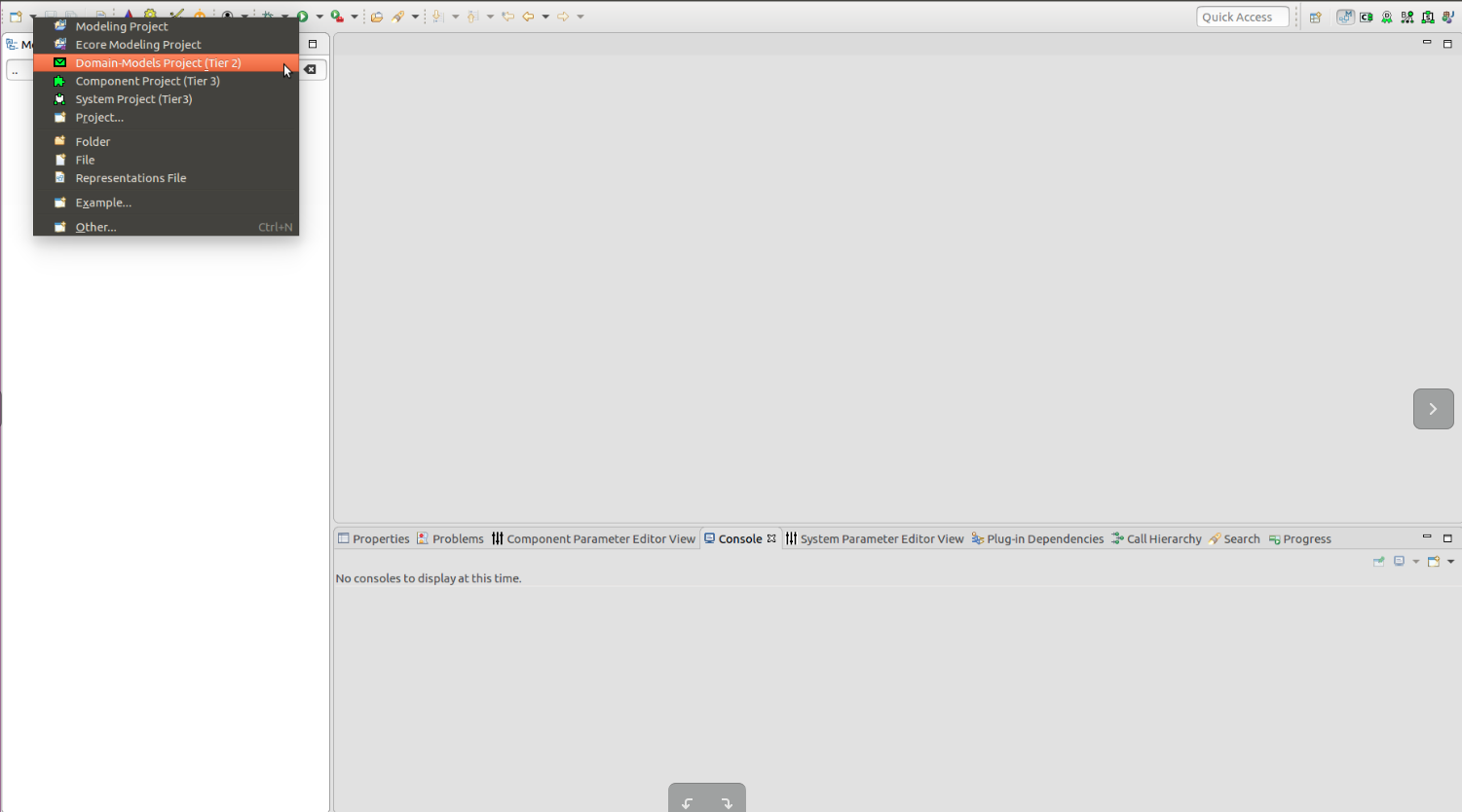
Create a new project : Domain Model Project Tier 2
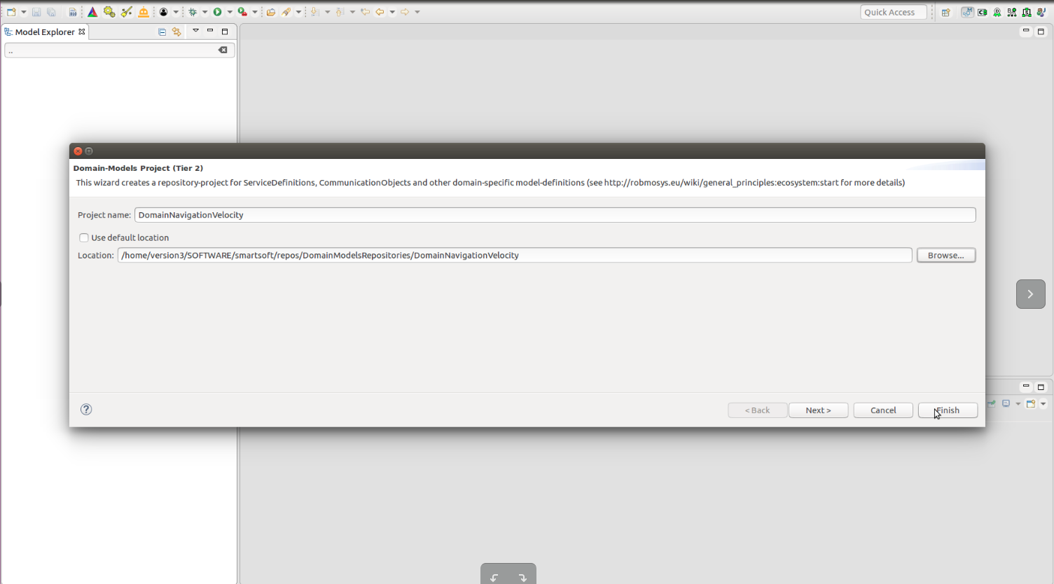
You can leave the option “Use default location” checked; it will put the project folder in the current workspace location. Optionally, you can select the folder as follows:
Creating a Communication Object
Modeling the communication object
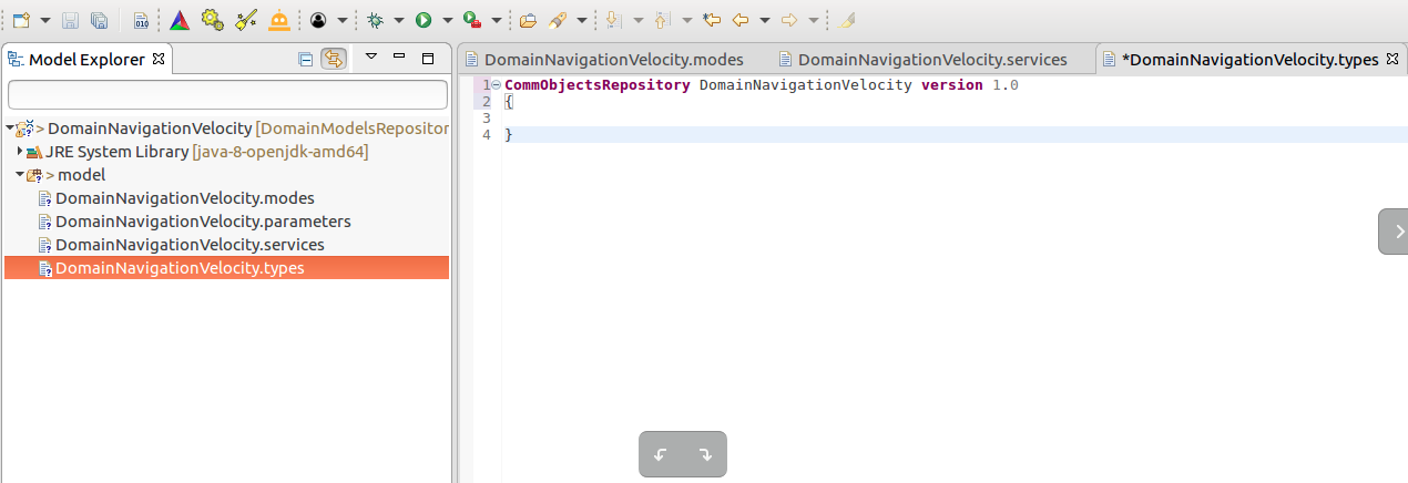
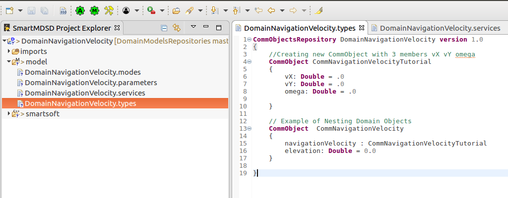
When a domain project is created, the toolchain automatically opens the .types file. This where we model the communication object:
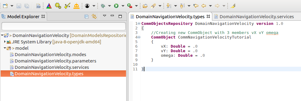
We will now model a communication object which specifies the velocity related parameters vX, vY and omega as doubles:
CommObject CommNavigationVelocityTutorial {
	vX: Double = .0
	vY: Double = .0
	omega: Double = .0
}
The first element (vX) is the name of the variable; the second is the data type; the third is the optional default value. Use Ctrl+Space to discover the options and available data types. Now, create the above model in the editor. It should look like this:
Nesting the Communication objects
For more complex objects and for the sake of reuse, one communication object can be nested in another. As shown in example below, CommNavigationVelocityTutorial object is nested inside CommNavigationVelocity. If you want to use object from other repositories, just use the fully qualified name. Autocompletion with CTRL+Space will support you in resolving the names.
Optional: Implement user access methods
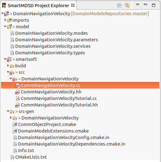
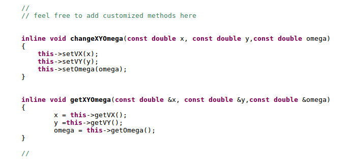
The SmartMDSD Toolchain automatically generates basic getters and setters for the communication objects. In some use-cases, you want to define custom access methods, e.g. to include a transformation or to set multiple values in one call. To do so, go to the smartsoft/src/ folder and edit the .hh and .cc files of your communication object. Watch out for the placeholder:
// feel free to add customized methods here
User access methods for setting and getting all values are showed in example below.
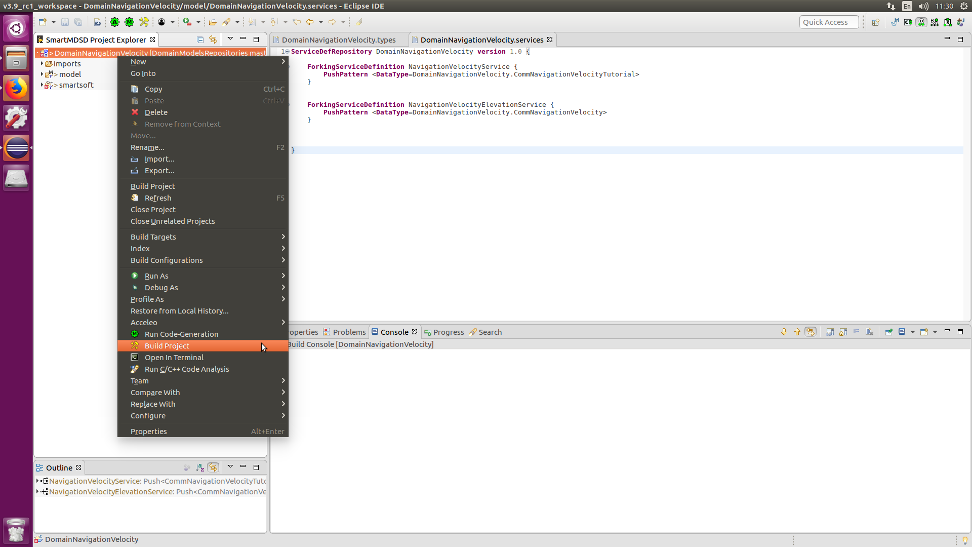
Compiling the project
Creating a Service Definition
We will now use the created communication object to model the service definition “NavigationVelocityService”:
ForkingServiceDefinition NavigationVelocityService {
		PushPattern <DataType=DomainNavigationVelocity.CommNavigationVelocityTutorial>
	}
In component to component communication, domain objects act as data and service definition act as rules regarding how the data is communicated / semantics. For example, using push pattern server can send the Domain object to client. In Query pattern server sends the data when a client specifically requests it. And in Event pattern, when a specific event occurs, the provider sends the data to one or more subscribers, who has noted interest (subscribed) to that specific event and condition.
The above code for a service definition model is a “forking” service. This means: The component providing such a service publishes the data to anyone interested in it (push). If you draw this on a sheet of paper, it will resemble a for; hene the name. The opposite is a join, where multiple components write data to one service port. We therefore select the push pattern (PushPattern <…>) among the set of available communication patterns. As data structure (DataType=…) , we select the previously modeled communication object. For more information on available communication patterns, see Communication Pattern Meta-Model, that describes the joyning/forking combinations.
Using the Service Definition in Components
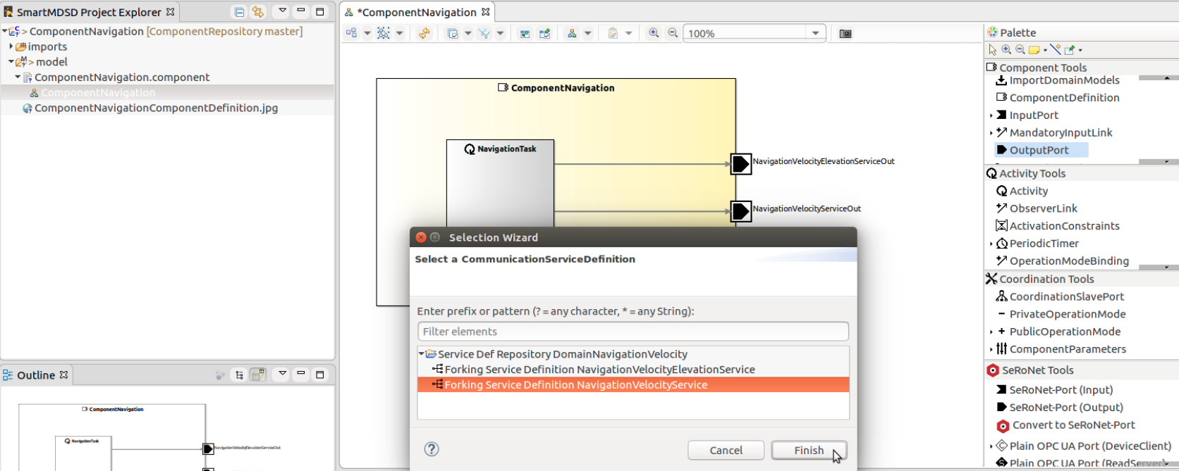
To use a service definition in a component model, import it first: click on ImportDomainModels in the palette. In the component model, create the input or output port according to your component needs (add the ports from the palette). A dialog will pop up to let you select a service definition. As shown in the picture, OutputPort NavigationVelocityServiceOut is modelled.
For example: In this case, if another component has InputPort with service definition NavigationVelocityService, then communication would be possible.


