Table of Contents
Creating your Own Real-World Deployment
In this tutorial you learn how to replace simulation components by real-world components. We do this by the example of the laser obstacle avoid (reactive navigation).
We start with the system you developed in Develop Your First System by Composing Software Components (reactive navigation with laser obstacle avoid). We do all the steps to make it work on a real robot instead of just in simulation. We focus on the differences between deployment for simulator and deployment for real-world. Finally, you end up at exactly the system for real-world deployment you have already seen in Deploy a Simple System onto a P3DX (or a Robotino).
Basic Information
| Level | Beginner |
|---|---|
| Role | System builder, but also other roles while browsing through the system's building blocks |
| Assumptions | Having completed the tutorial Deploy a Simple System onto a P3DX (or a Robotino) |
| System Requirements | Virtual Machine Image Installed, see ready-to-go virtual machine |
| You will learn | - how to convert a system from simulation to a physical robot setting - how to deploy a system to a physical robot via the SmartMDSD toolchain - how to start the deployed system, run the physical robot, and stop the system |
| Options |
Description
We start by creating a new system project by copying an existing project. Then we modify the newly created system project to make it work with the real robot equipped with a real laser sensor. These modifications include modifying the System Architecture Model, the Target Platform Model, the Deployment Model and System Parameters. Finally, we deploy the developed system onto a real robot and execute it.
Creating a System Project
Step 1.a: In this step, we create the system project SystemP3dxLaserObstacleAvoidRealWorld by copying and renaming the SystemLaserObstacleAvoidP3dxWebotsSimulator project. We use the following bash code snippet for this. Download the following code snippet to ${SMART_ROOT_ACE}/repos/SystemRepository.
- copyAndRenameMDSDProjects.sh
#!/bin/bash

function help_exit(){
    echo "usage: bash $0 <old project name> <new project name>"
    echo "Do not pass path names as arguments!!"
    echo -e '\033[0;31m' "Exiting the script with failure!!" '\033[0m'
    exit 1
}

if [ "$#" -ne 2 ] || [ "$2" == "" ]; then
    help_exit
fi

if [[ ! -d "${1}" ]]; then
    echo -e '\033[0;31m' "[ERROR] There is no project with the name $1 " '\033[0m'
    help_exit
    exit 1
fi

if [  -d "${2}"  ]; then
    echo -e '\033[0;31m' "[ERROR] A project already exists with the name $2, try with a different name for target project" '\033[0m'
    help_exit
    exit 1
fi

OPWD=$(pwd)
OLD=$1
NEW=$2

echo "Copy component $OLD to $NEW? [y/n]"
read answer

if [ "$answer" != "y" ]; then
    echo "aborting"
    exit 1
fi

cp -r $OLD $NEW
cd $NEW

rm -rf bin/ smartsoft/build/

for I in $(find -name "*$OLD*"); do
    mv $I $(echo $I| sed "s/$OLD/$NEW/g");
done

for I in $(grep -Rl $OLD * .cproject .project); do
    sed -i "s/$OLD/$NEW/g" $I;
done

cd $OPWD
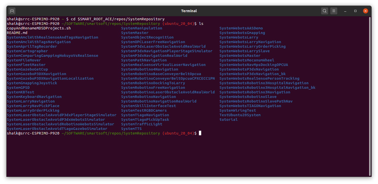
Make sure that you have downloaded the script copyAndRenameMDSDProjects.sh to ${SMART_ROOT_ACE}/repos/SystemRepository by executing the following commands.
cd $SMART_ROOT_ACE/repos/SystemRepository
ls
Now you should see the script copyAndRenameMDSDProjects.sh and the available systems as follows.
Now use the script to create the new project as follows:
#usage : bash copyAndRenameMDSDProjects.sh <old project> <new project>

bash copyAndRenameMDSDProjects.sh SystemLaserObstacleAvoidP3dxWebotsSimulator SystemP3dxLaserObstacleAvoidRealWorld

#if you already have the project SystemP3dxLaserObstacleAvoidRealWorld, use another name for new project (for example SystemP3dxLaserObstacleAvoidRealWorldNew).
#bash copyAndRenameMDSDProjects.sh SystemLaserObstacleAvoidP3dxWebotsSimulator SystemP3dxLaserObstacleAvoidRealWorldNew
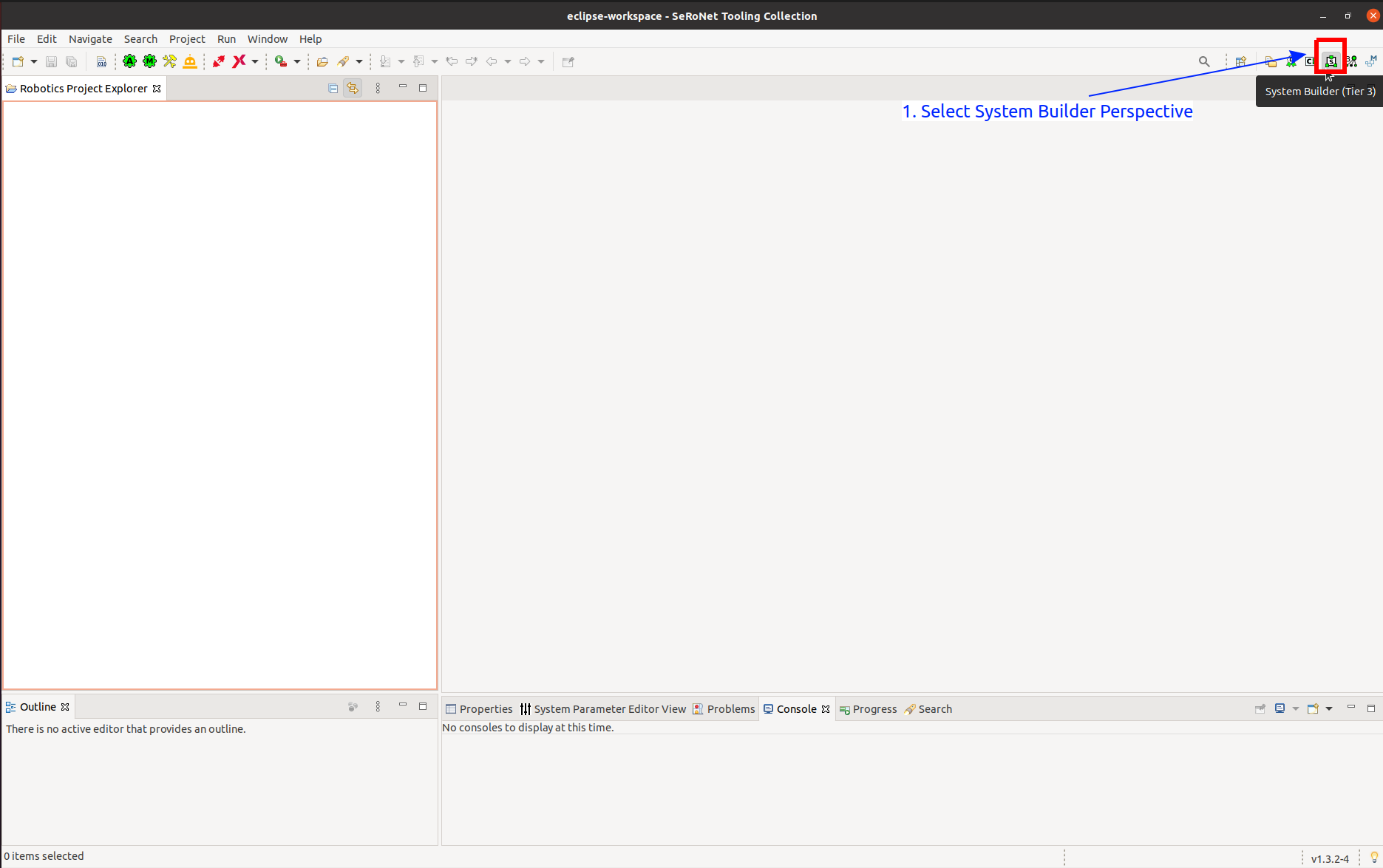
Now we need to import the newly created system project in the Toolchain. Start the Toolchain and select the System Builder (Tier 3) perspective as shown below:
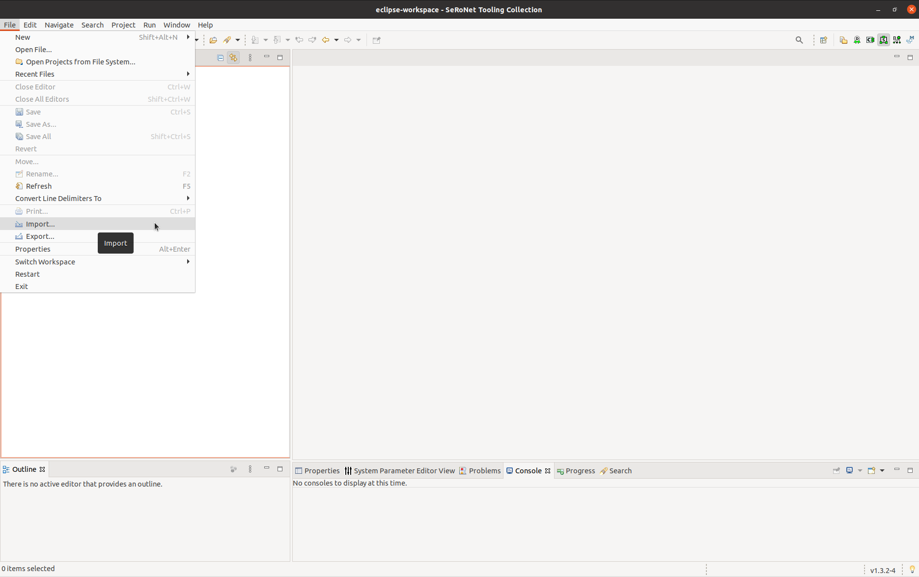
Select File → Import.
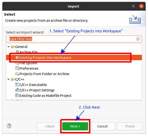
Select Existing Projects into Workspace and click on Next.
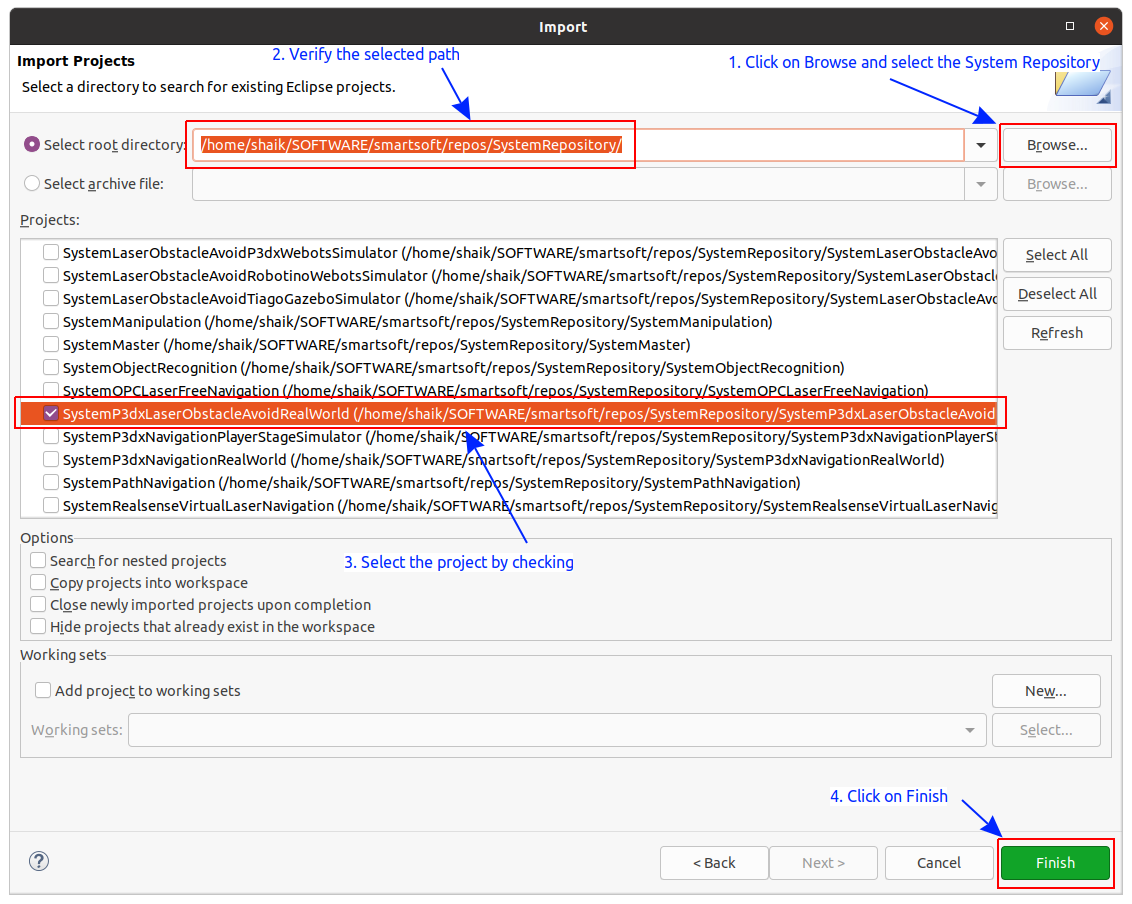
Browse to the folder ${SMART_ROOT_ACE}/repos/SystemRepository and select the newly created project and click on Finish.
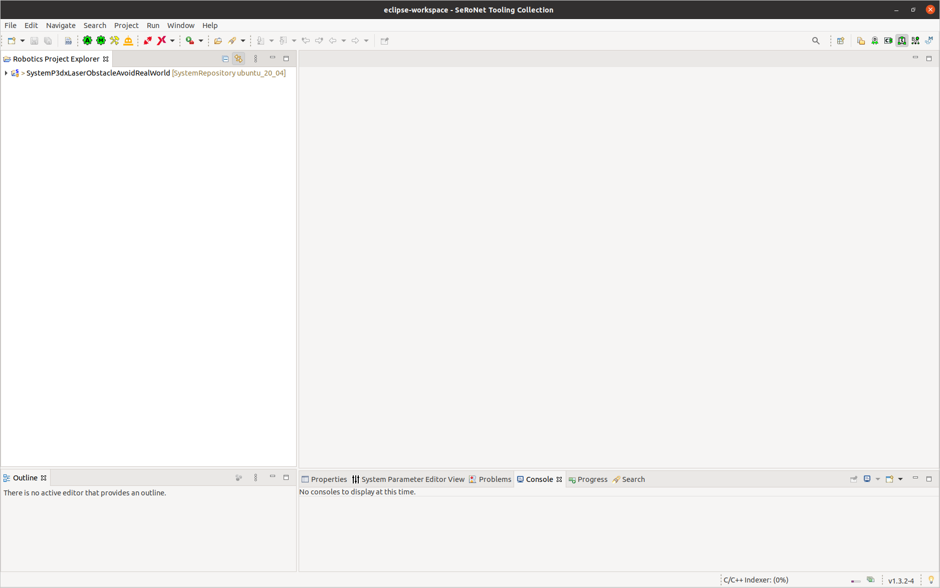
Now you will be able to the imported project in the workspace as follows:
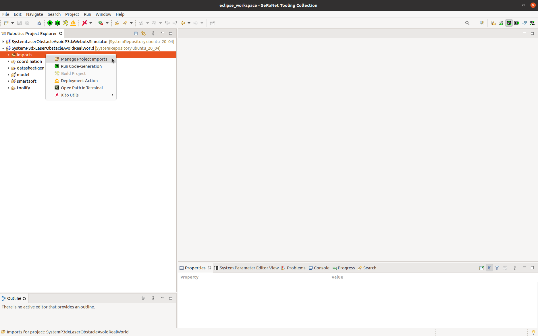
Step 1.b: We need to modify the project imports. To do this expand the project by double-clicking. Right-click on imports folder and select manage Project Imports.
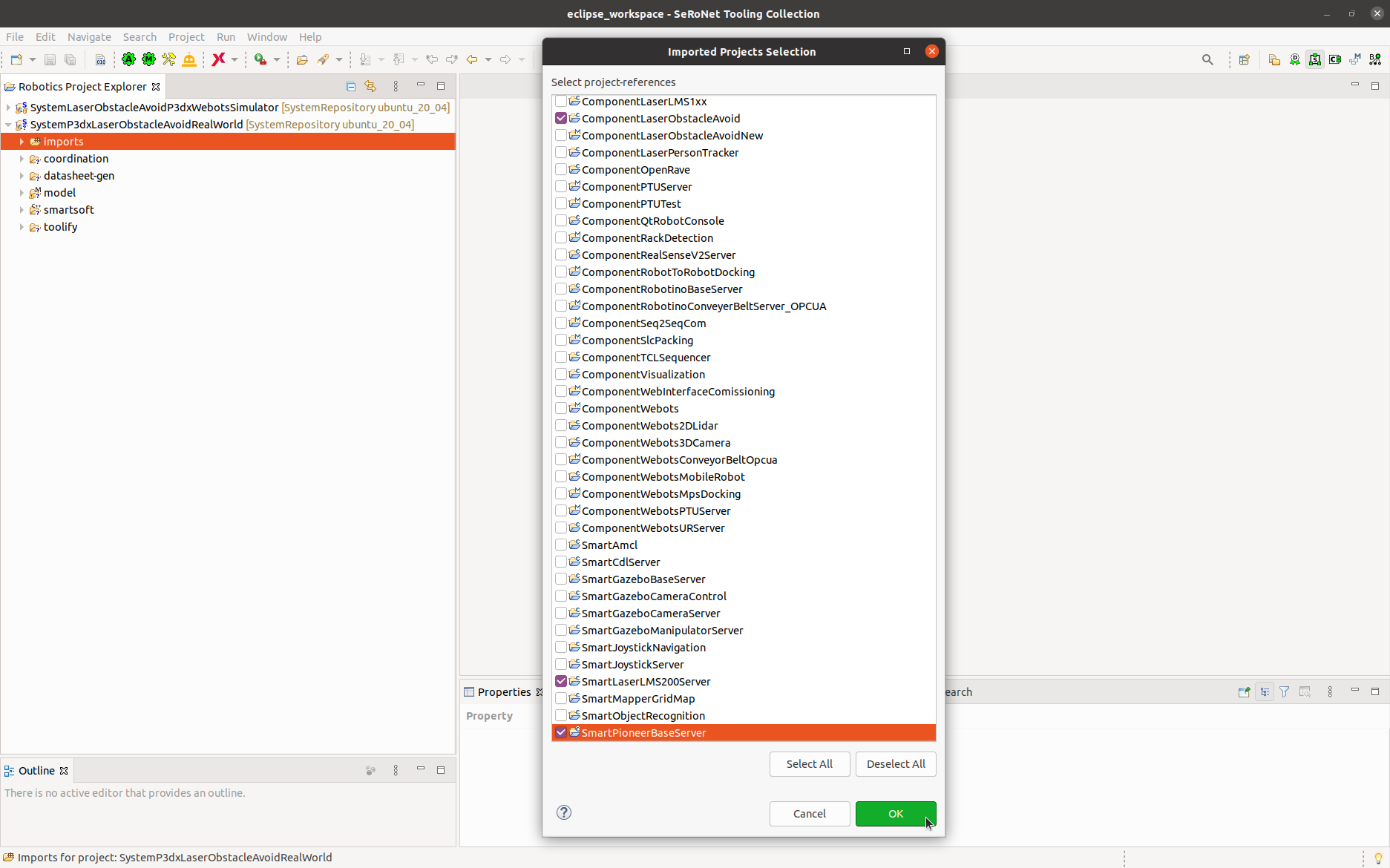
Now you see the set of components that are available in your workspace. Deselect the components specific to webots(i.e ComponentWebots, ComponentWebots2DLidar, ComponentWebotsMobileRobot) and select the components specific to real-world (i.e SmartLaserLMS200Server, SmartPioneerBaseServer) as indicated in the figure below:
Modifying System Architecture Model
Step 2.a: Open the system architecture by double-clicking on system architecture model i.e SystemP3dxLaserObstacleAvoidRealWorldComponentArchitecture.
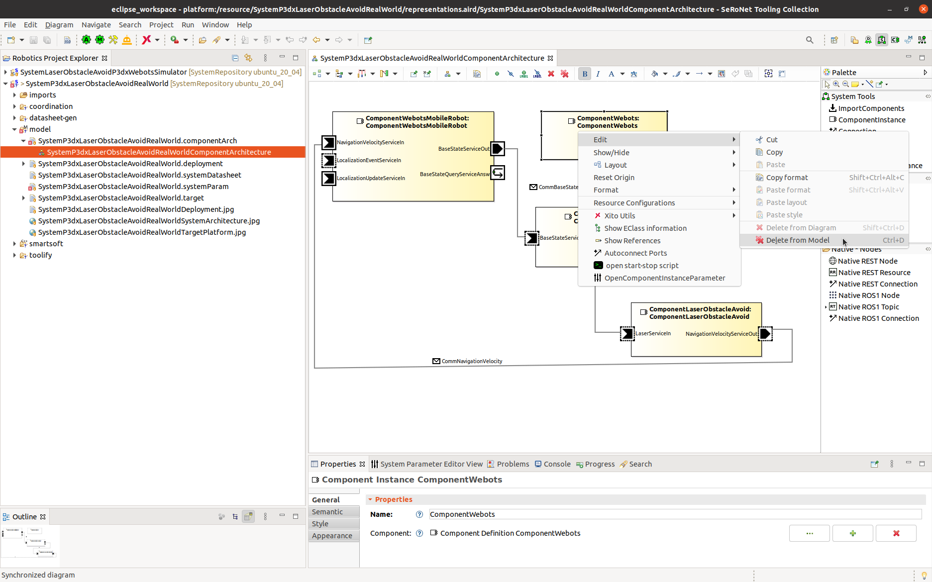
Delete the instance ComponentWebots from the system architecture. Select the component → right-click → Edit →Delete from Model as shown in the figure below:
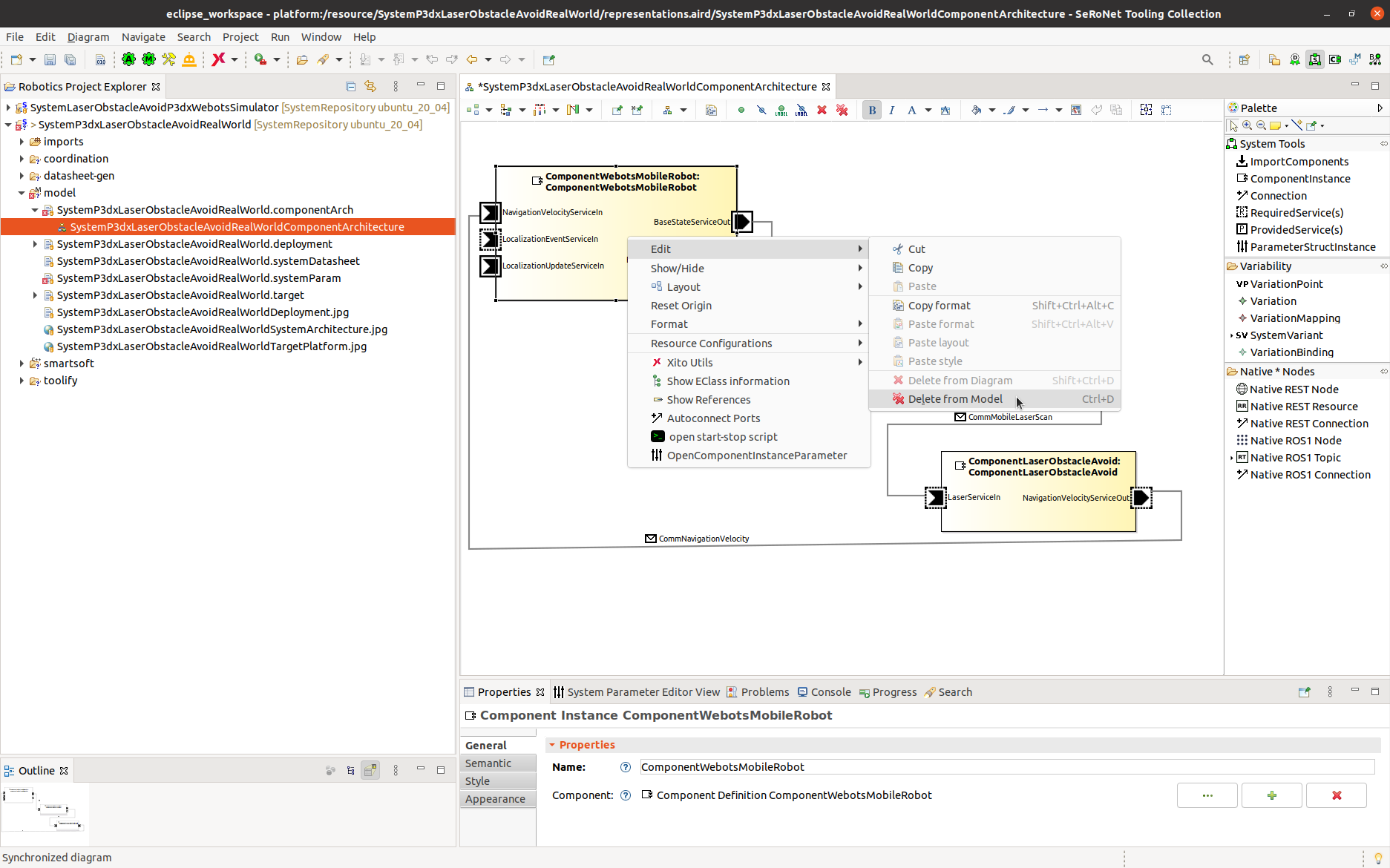
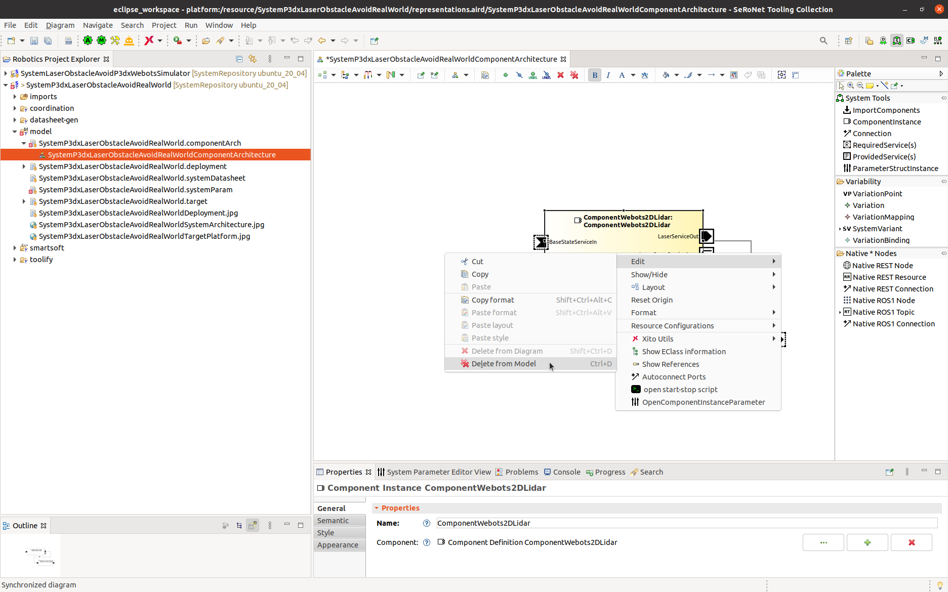
In a similar way, delete the instances of ComponentWebotsMobileRobot and ComponentWebots2DLidar from the system architecture as shown in the figure below:
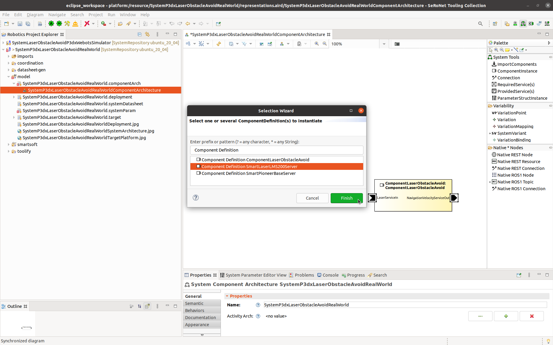
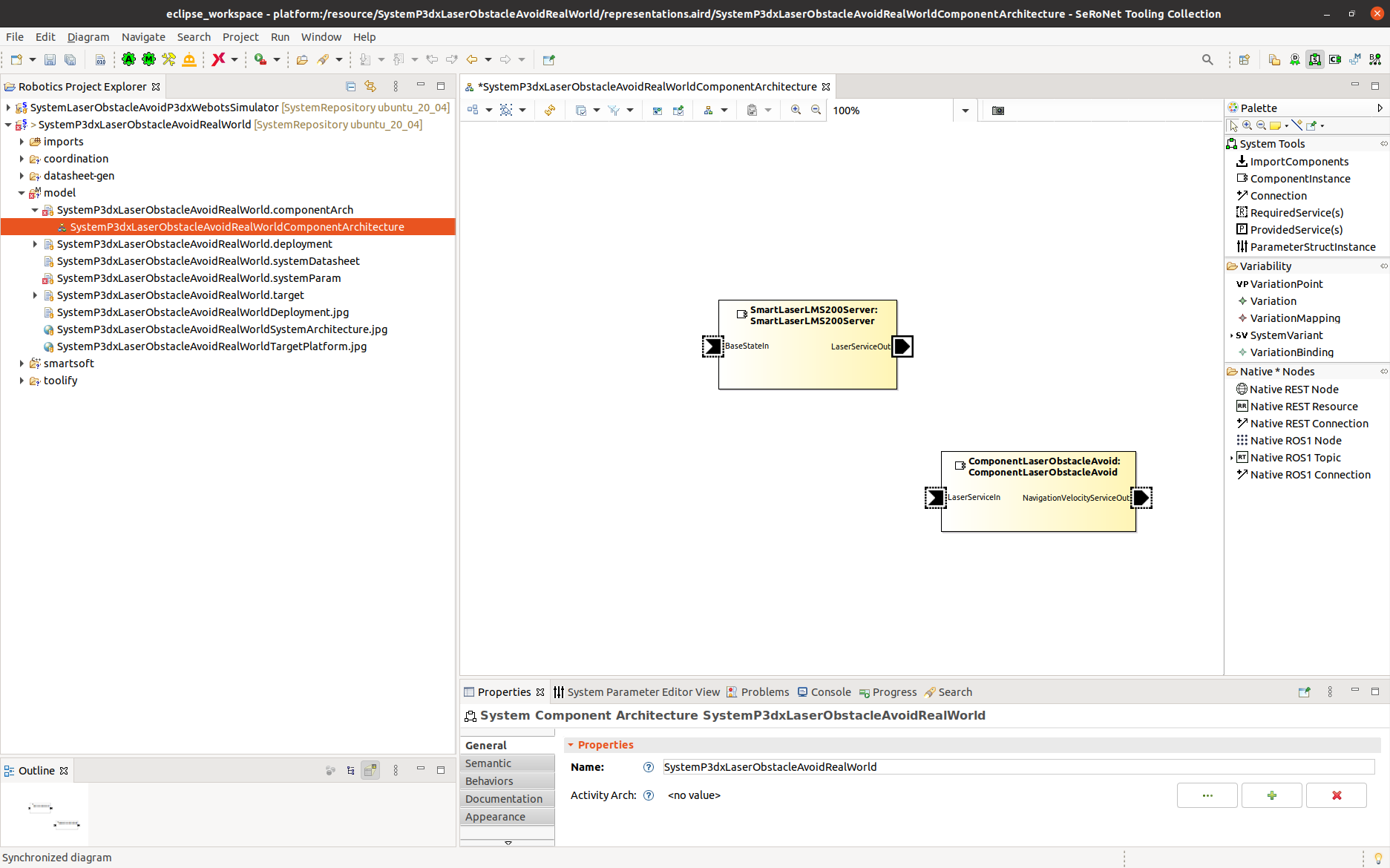
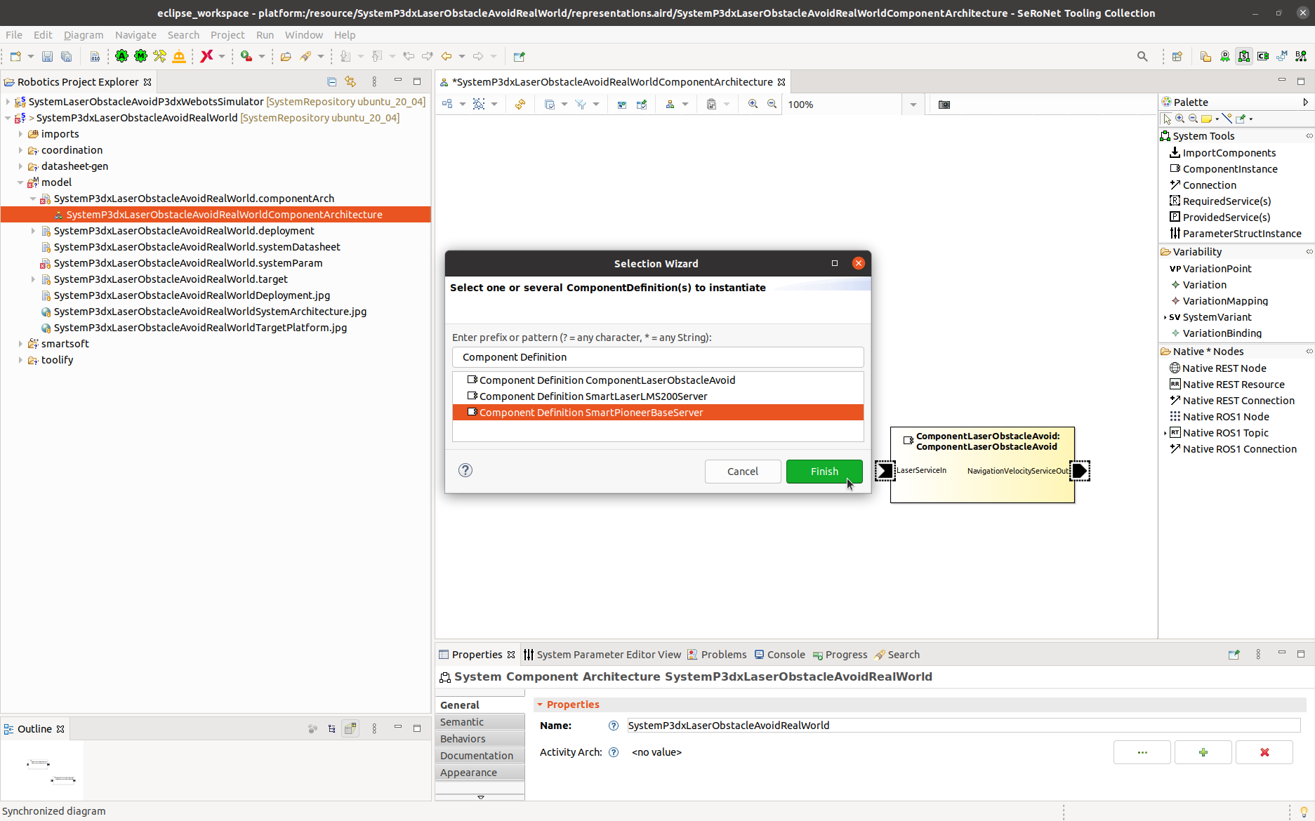
Step 2.b: Now add the instances of the components used for real-world system. Drag the ComponentInstance from the System Tools into the system architecture file. A selection wizard opens. Select the Component Definition SmartLaserLMS200Server and click Finish.
Now the SmartLaserLMS200Server instance got added. You can rearrange the ports and the port names to get the following result:
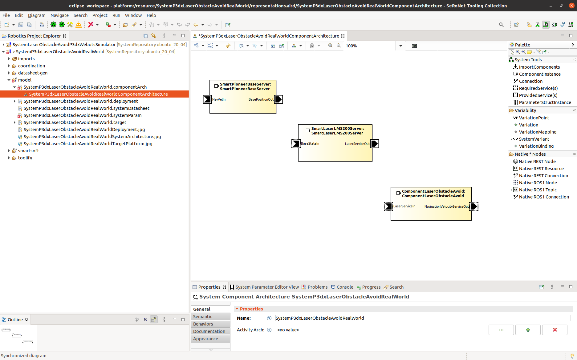
Similarly, add the instance of SmartPioneerBaseServer to the system architecture as shown in the figure below:
You can rearrange the ports and the port names. You can delete the unused ports to get the following result:
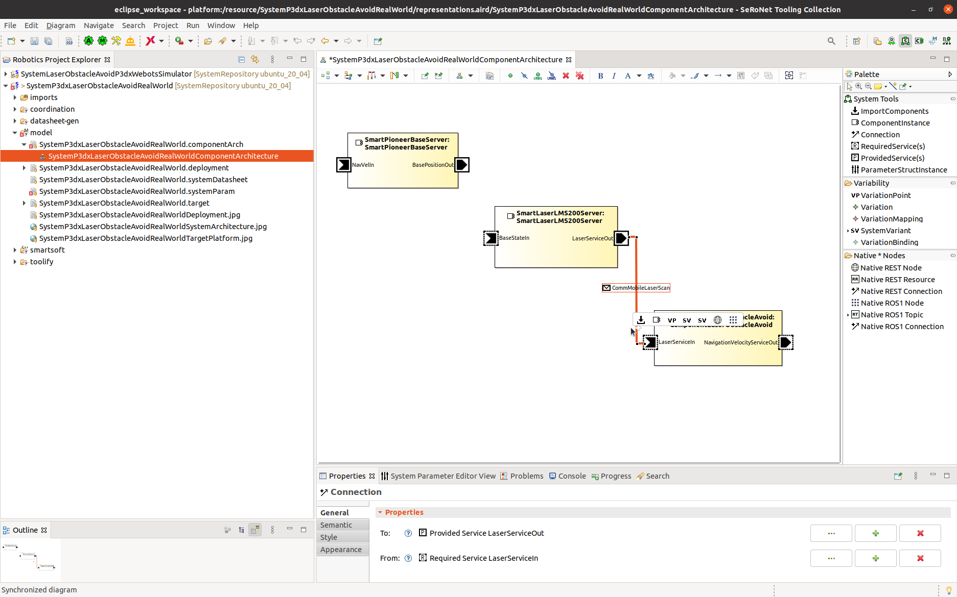
Step 2.c: We now connect the ports of the components. Drag the Connection from the System Tools to the LaserServiceIn port of the ComponentLaserObstacleAvoid and click and continue to drag to the LaserServiceOut port of the SmartLaserLMS200Server. You can rearrange the wiring visually to get the following result:
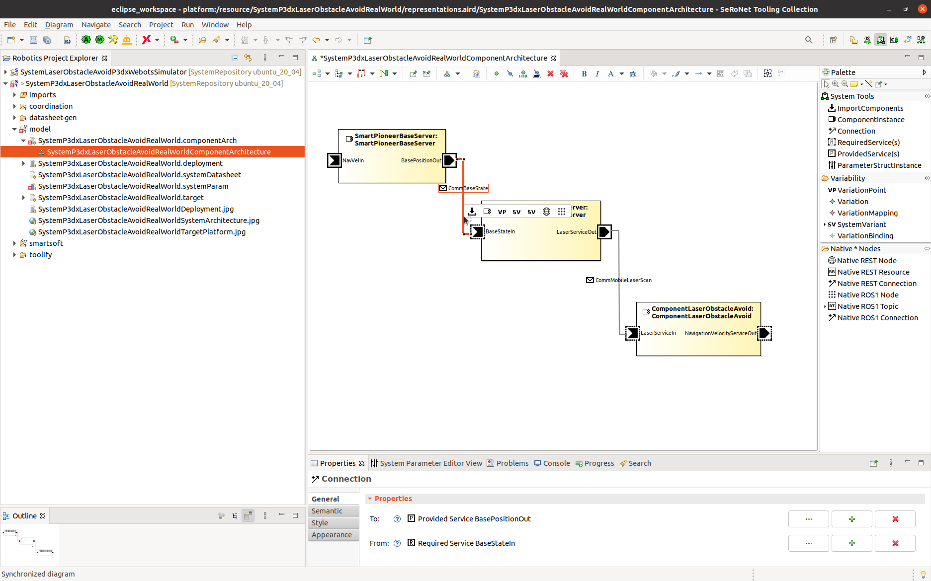
Drag the Connection from the System Tools to the BaseStateServiceIn port of the SmartLaserLMS200Server and click and continue to drag to the BaseStateServiceOut port of the SmartPioneerBaseServer. You can rearrange the wiring visually to get the following result:
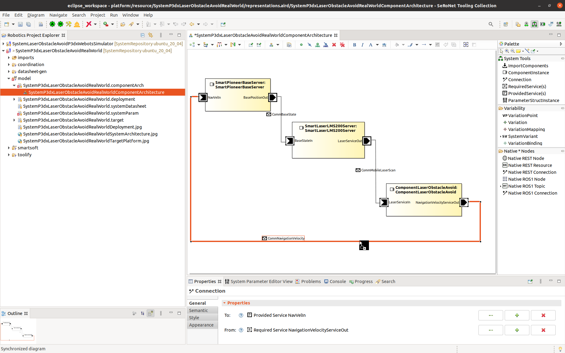
Drag the Connection from the System Tools to the NavigationVelocityServiceOut port of the ComponentLaserObstacleAvoid and click and continue to drag to the NavigationVelocityServiceIn port of the SmartPioneerBaseServer. You can rearrange the wiring visually to get the following result:
Modifying Target Platform Model
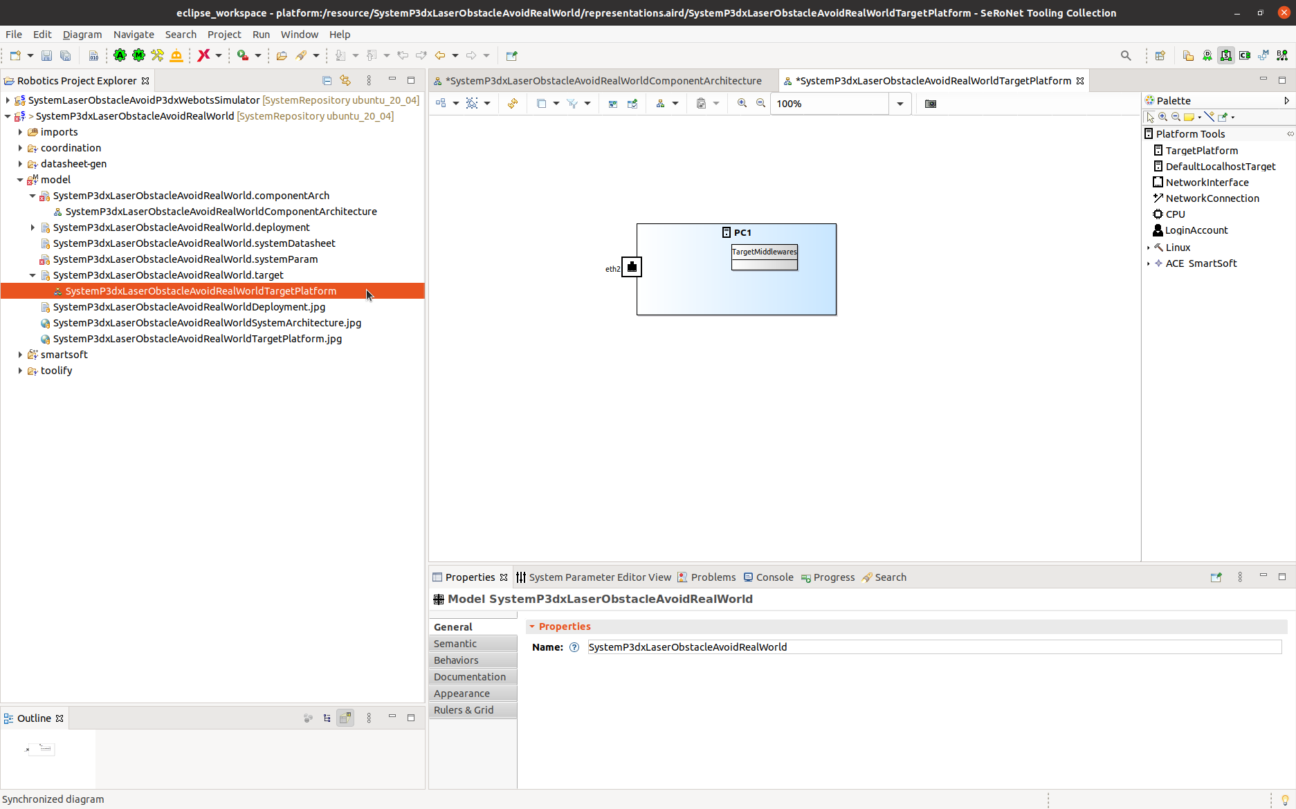
Step 3.a: Open the target platform model by double clicking the target platform model:
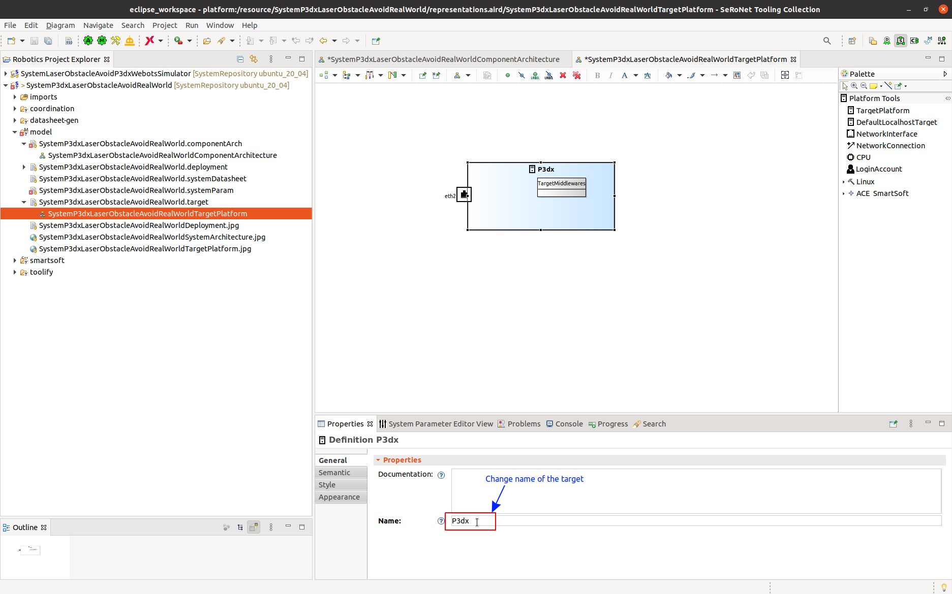
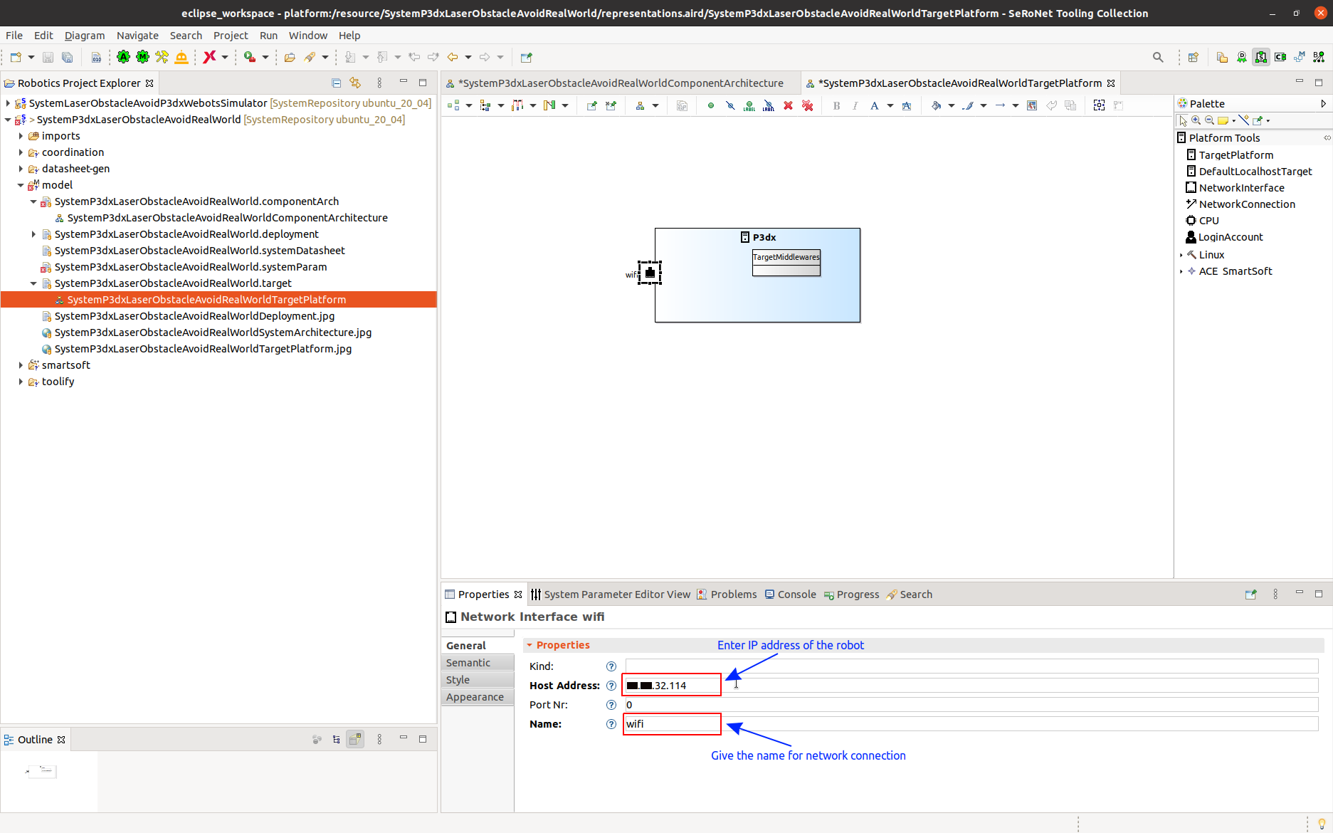
Optionally, you can change the target name from its default name “PC1”. Here we use the name “P3dx” as follows:
Step 3.b: Change Network Connection details. Since our system runs on the Pioneer3dx robot, we configure the host address as IP address of the robot. This IP address is used during the deployment to deploy the system files onto the robot. This IP address is used to remotely connect to the robot using vncviewer. Network connection name is user given name, here we gave the name “wifi”.
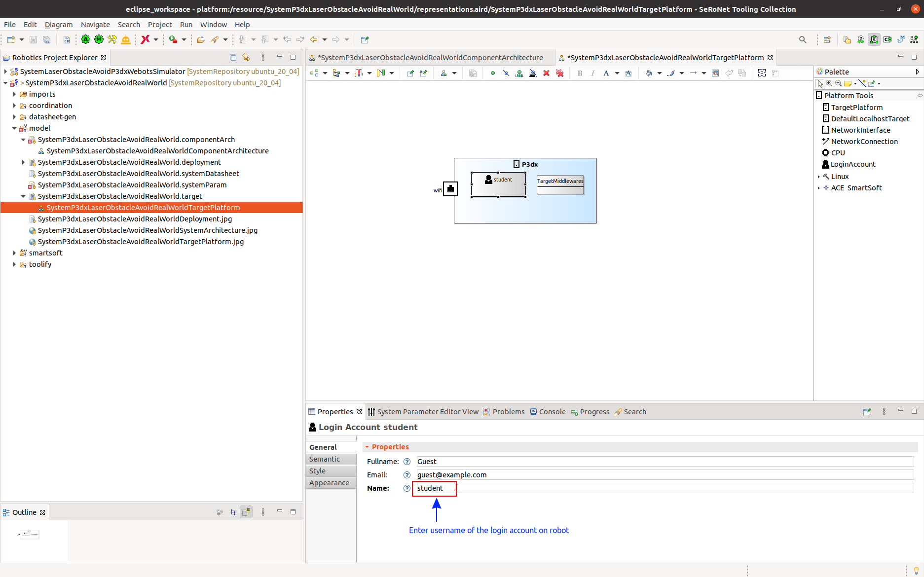
Step 3.c: We now have to add the username of a login account on the target system(i.e here computer on robot). This is used later on in the deployment step. During the deployment step, you need the password for this user account.
Modifying Deployment Model
Step 4.a: Open the target platform model by double clicking on the target platform model as shown below:
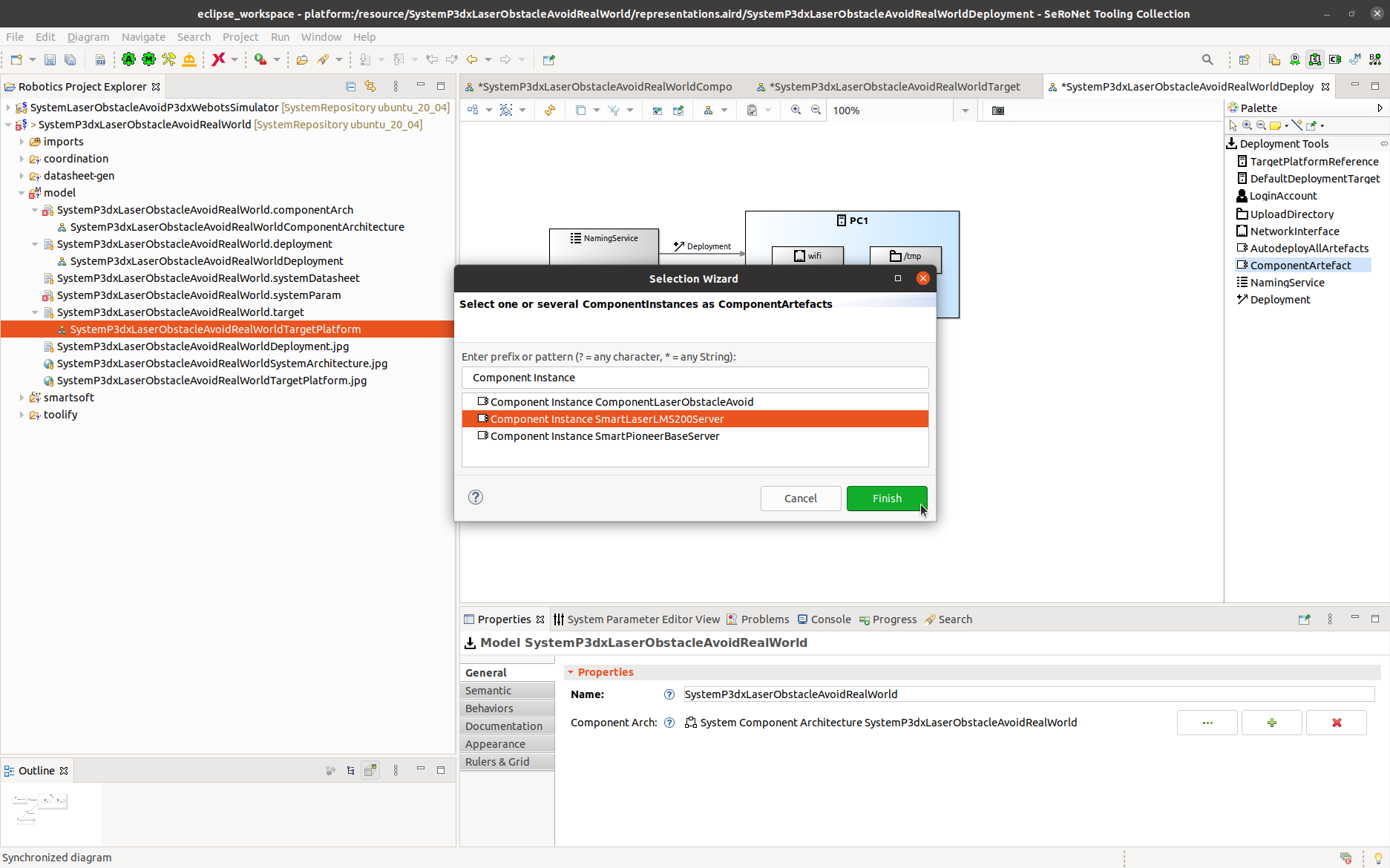
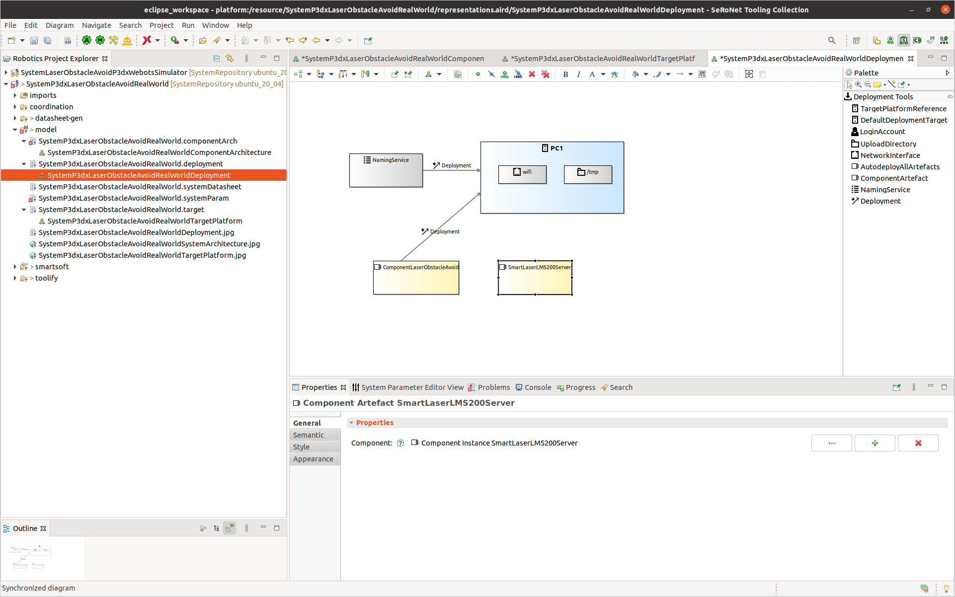
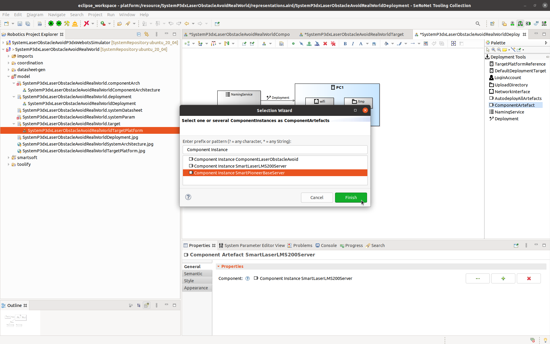
Step 4.b: Add the ComponentArtefacts by dragging from the Deployment Tools. This opens a wizard where you select a component instance SmartLaserLMS200Server.
After adding SmartLaserLMS200Server artifact, you will see the following result:
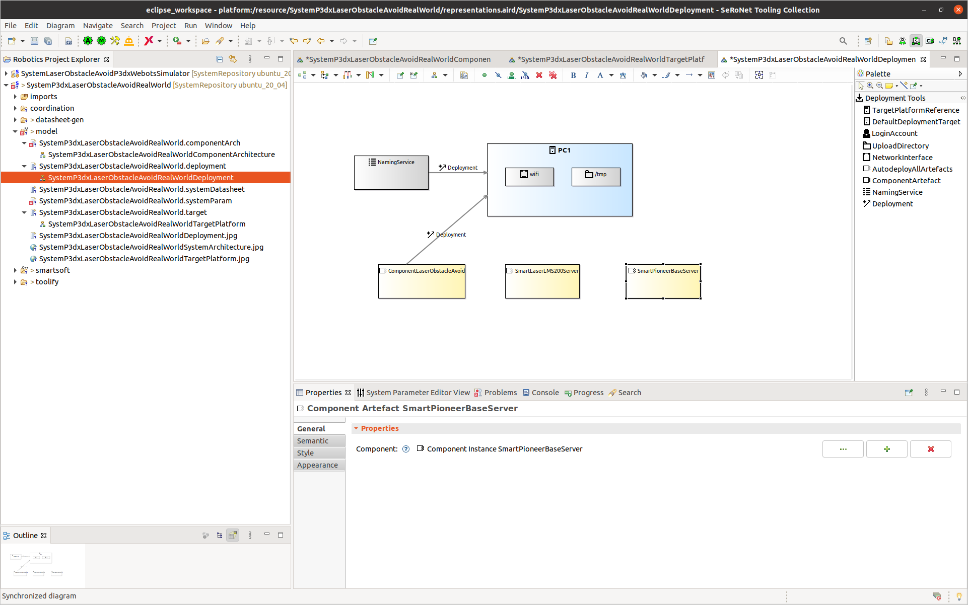
Similarly add SmartPioneerBaseServer artifact.
After adding SmartPioneerBaseServer artifact, you will see the following result:
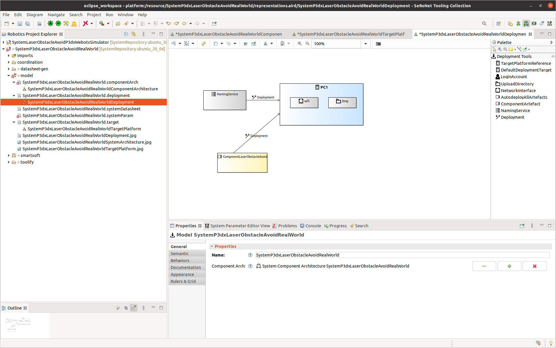
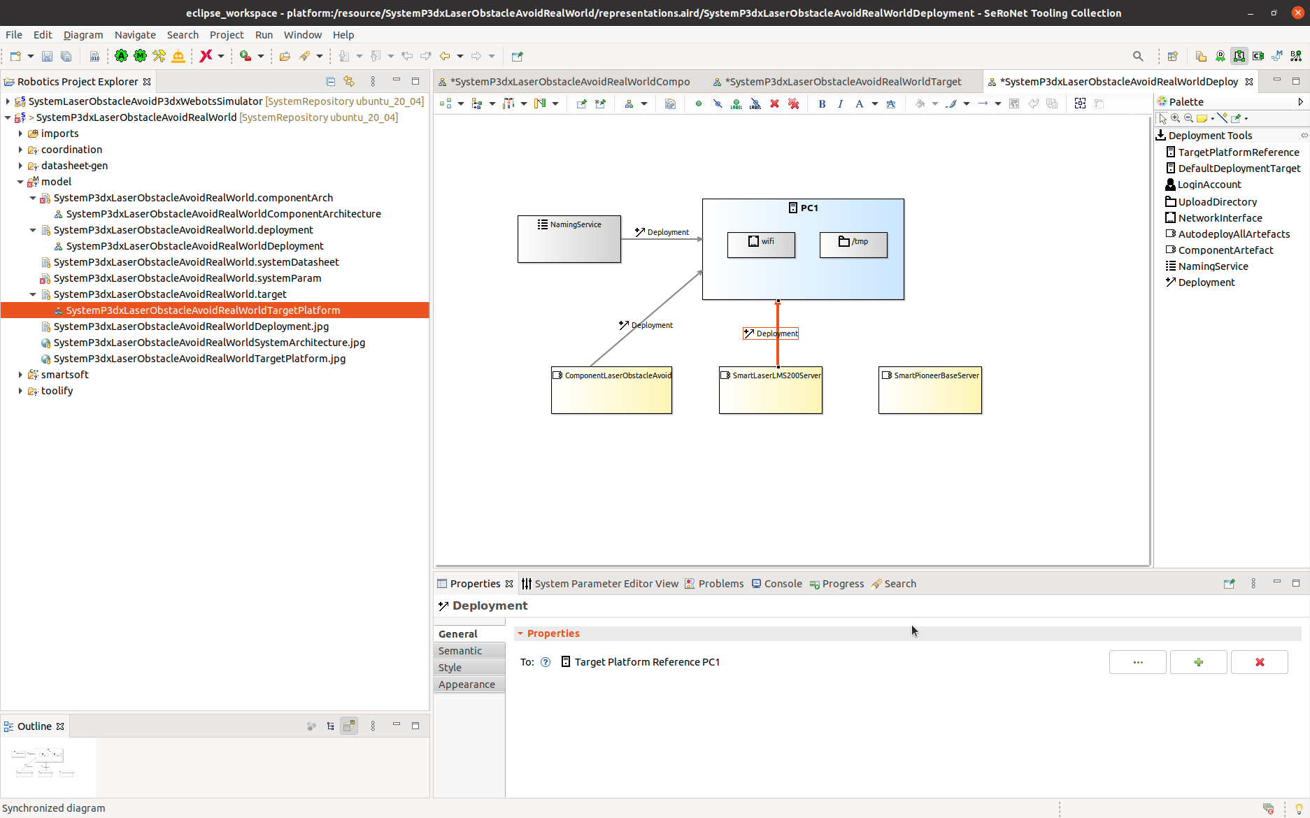
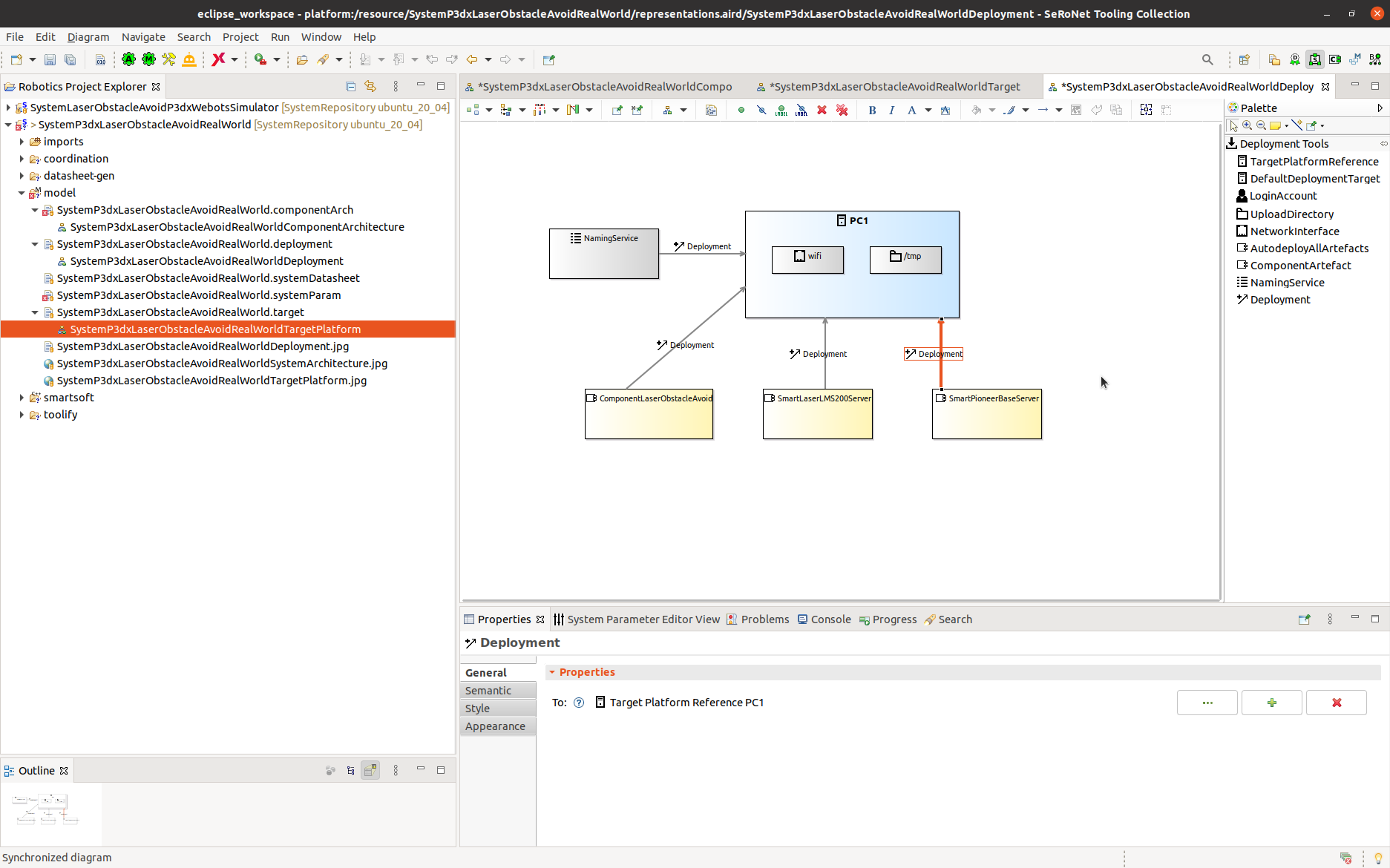
Step 4.c: We now need to assign the component instances to the target platform. This specifies where the component instance gets deployed and executed. You do the connections by dragging the Deployment from the Deployment Tools onto the Component instance and then select the target. You will see the deployment connection as shown below:
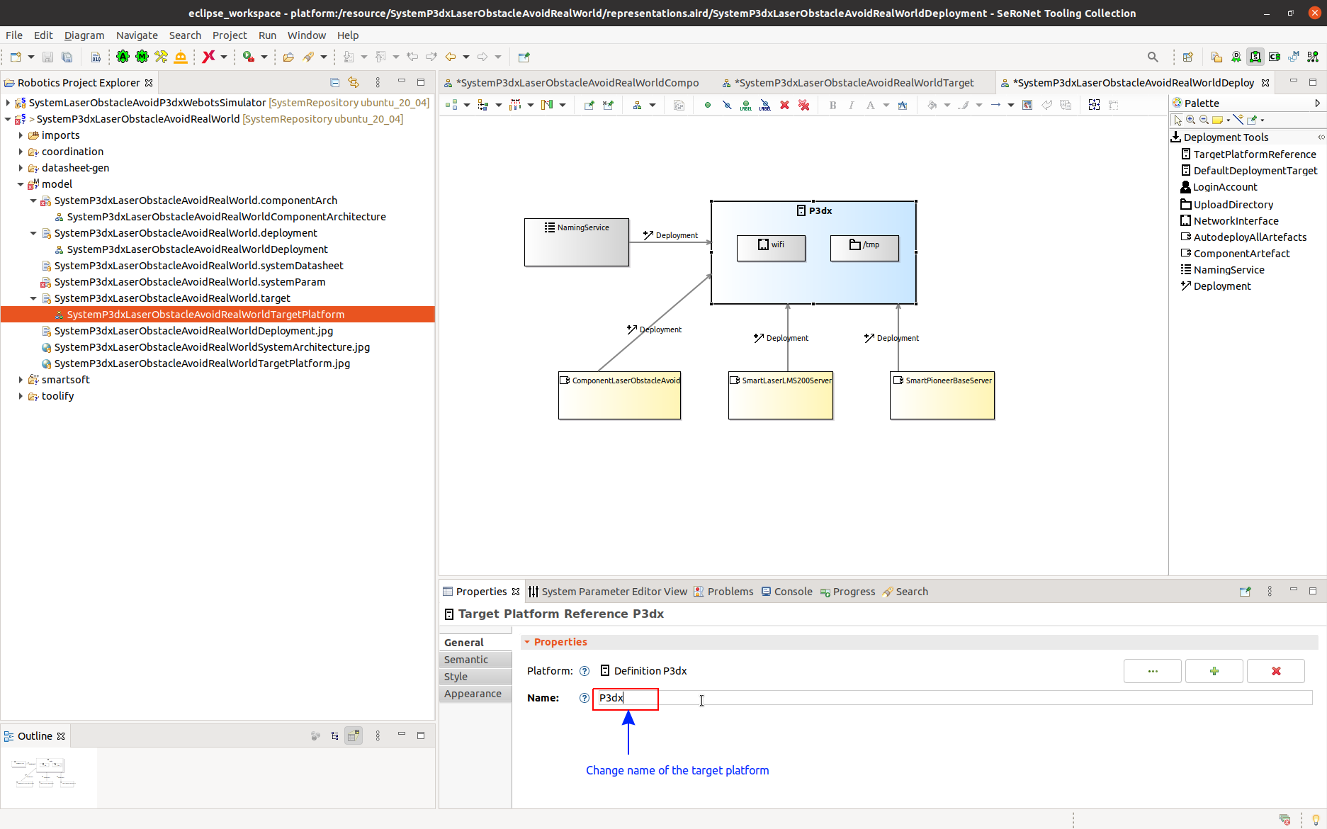
Now, we have to update the name of the target platform in deployment model. To do this, select the target platform and change the Name in the properties tab as “P3dx” and press enter. This name must be same as the name given in the setp 3.a. After updating the target name the result be as follows:
Modifying System Parameters
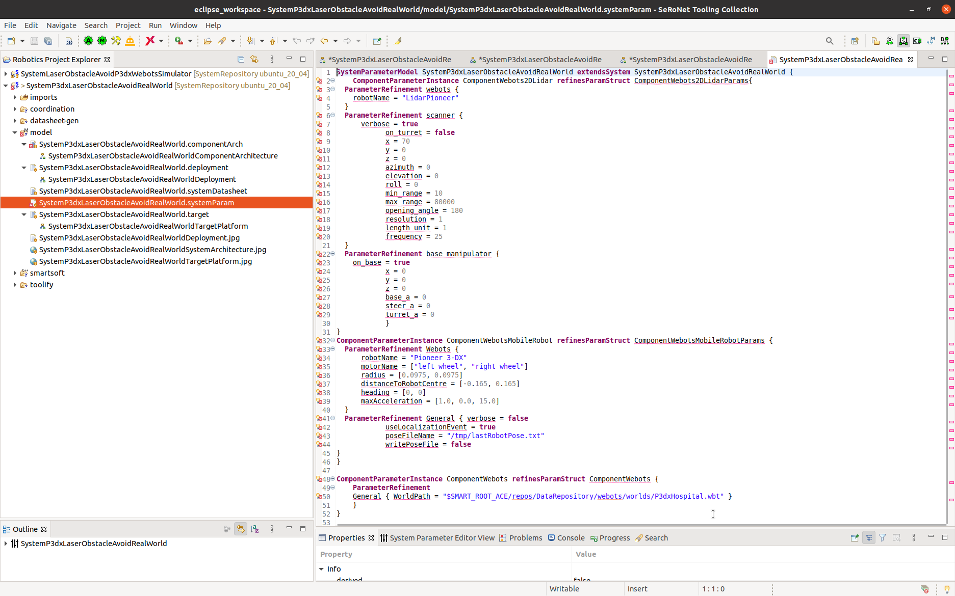
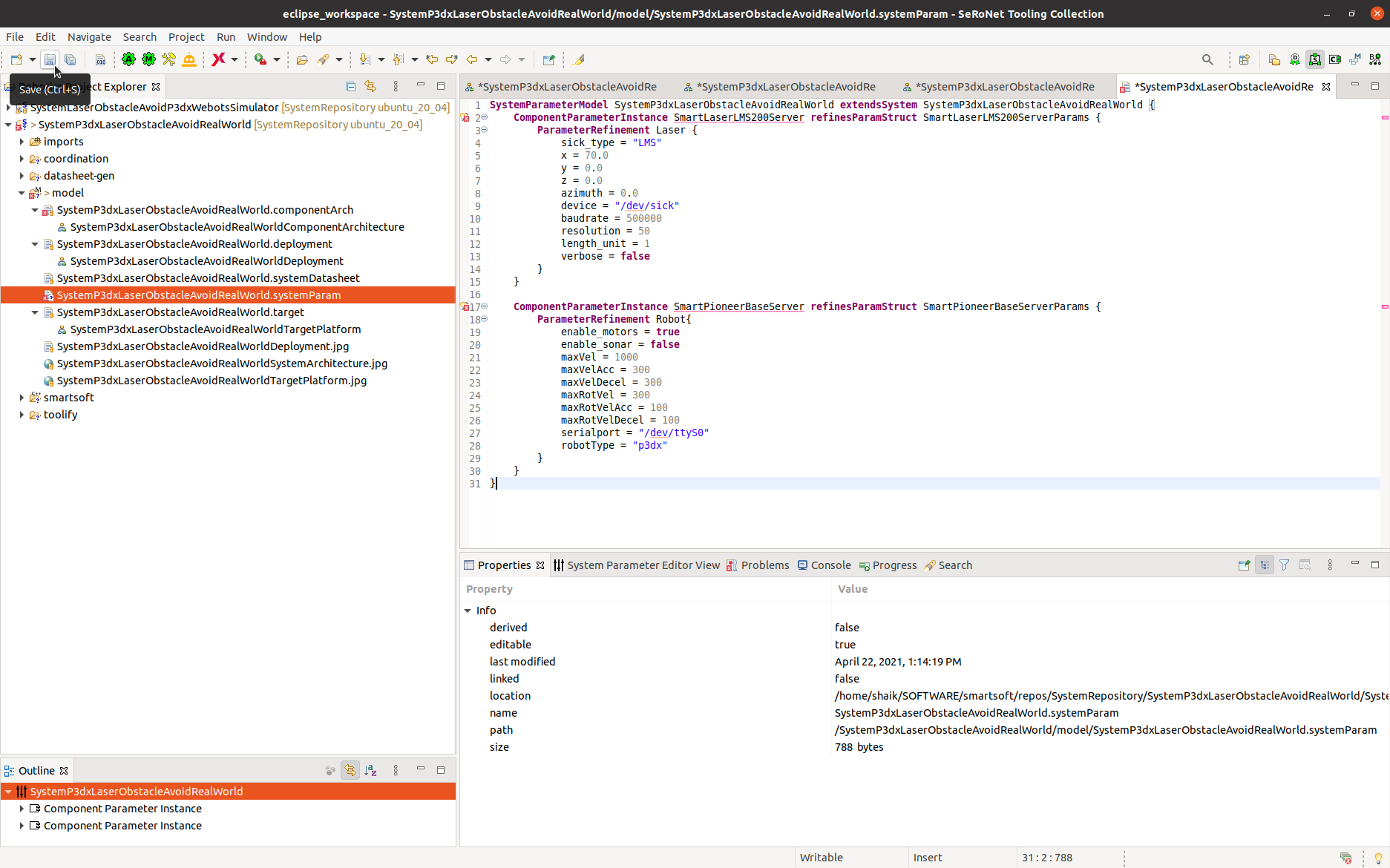
Step 5.a: Open the system parameter modeler. Now you see the system parameter file:
Step 5.b: Copy & Paste the following content into your system parameter file:
- SystemP3dxLaserObstacleAvoidRealWorld.systemParam
SystemParameterModel SystemP3dxLaserObstacleAvoidRealWorld extendsSystem SystemP3dxLaserObstacleAvoidRealWorld {
	ComponentParameterInstance SmartLaserLMS200Server refinesParamStruct SmartLaserLMS200ServerParams {
		ParameterRefinement Laser {
			sick_type = "LMS"
			x = 70.0
			y = 0.0
			z = 0.0
			azimuth = 0.0
			device = "/dev/sick"
			baudrate = 500000
			resolution = 50
			length_unit = 1
			verbose = false
		}
	}

	ComponentParameterInstance SmartPioneerBaseServer refinesParamStruct SmartPioneerBaseServerParams {
		ParameterRefinement Robot{
			enable_motors = true
			enable_sonar = false
			maxVel = 1000
			maxVelAcc = 300
			maxVelDecel = 300
			maxRotVel = 300
			maxRotVelAcc = 100
			maxRotVelDecel = 100
			serialport = "/dev/ttyS0"
			robotType = "p3dx"
		}
	}
}
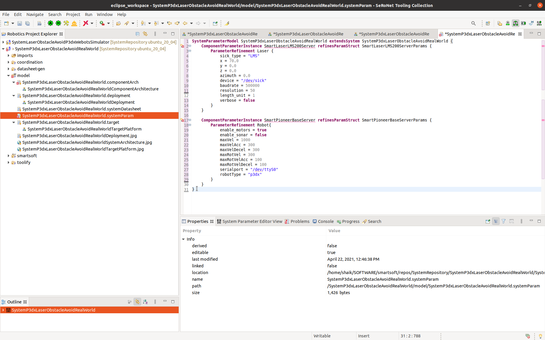
Now SystemP3dxLaserObstacleAvoidRealWorld.systemParam should look like as follow:
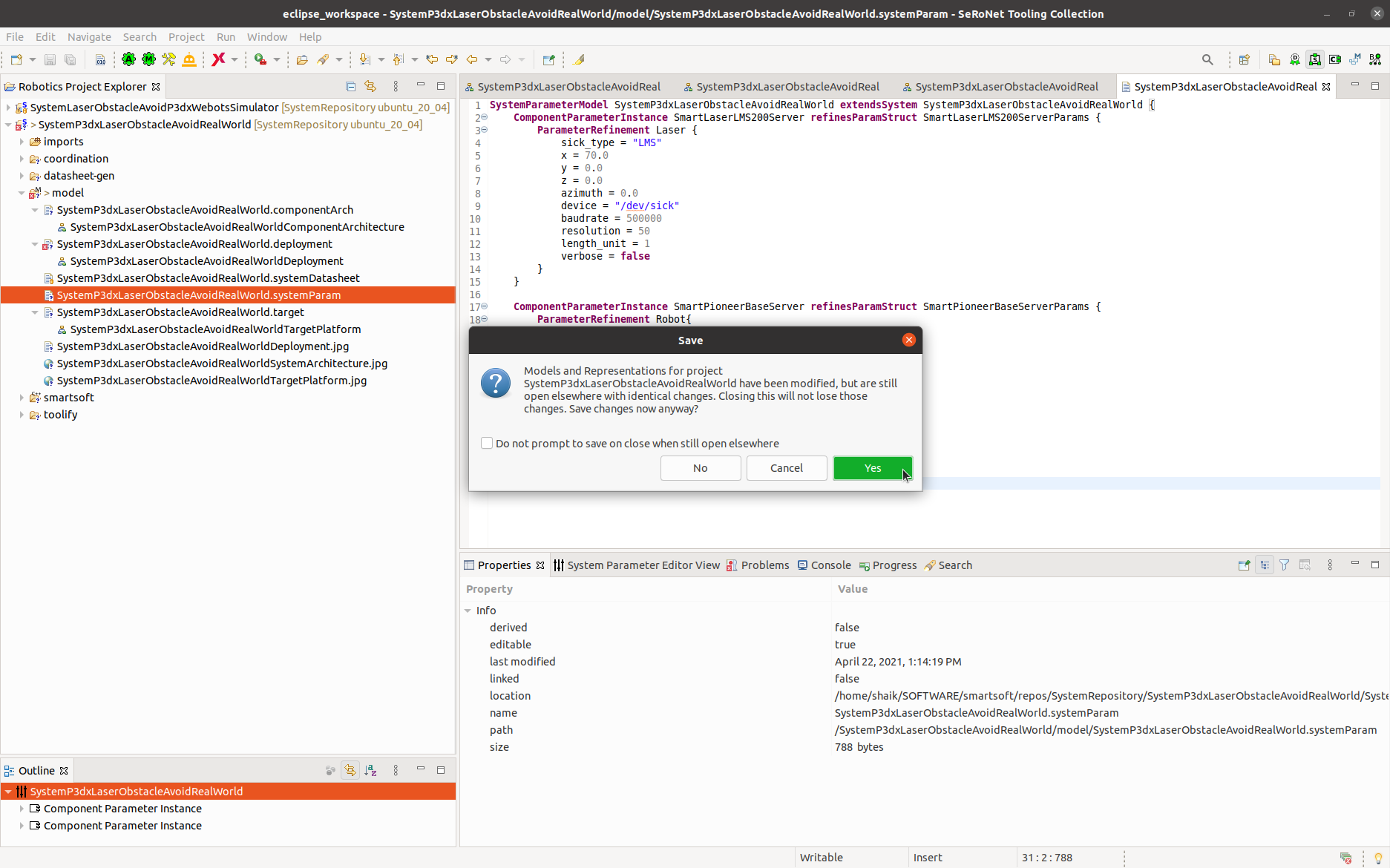
All the modification are done and now save all the models by click Save all as shown :
A popup comes as show, select “Yes”.
Deployment
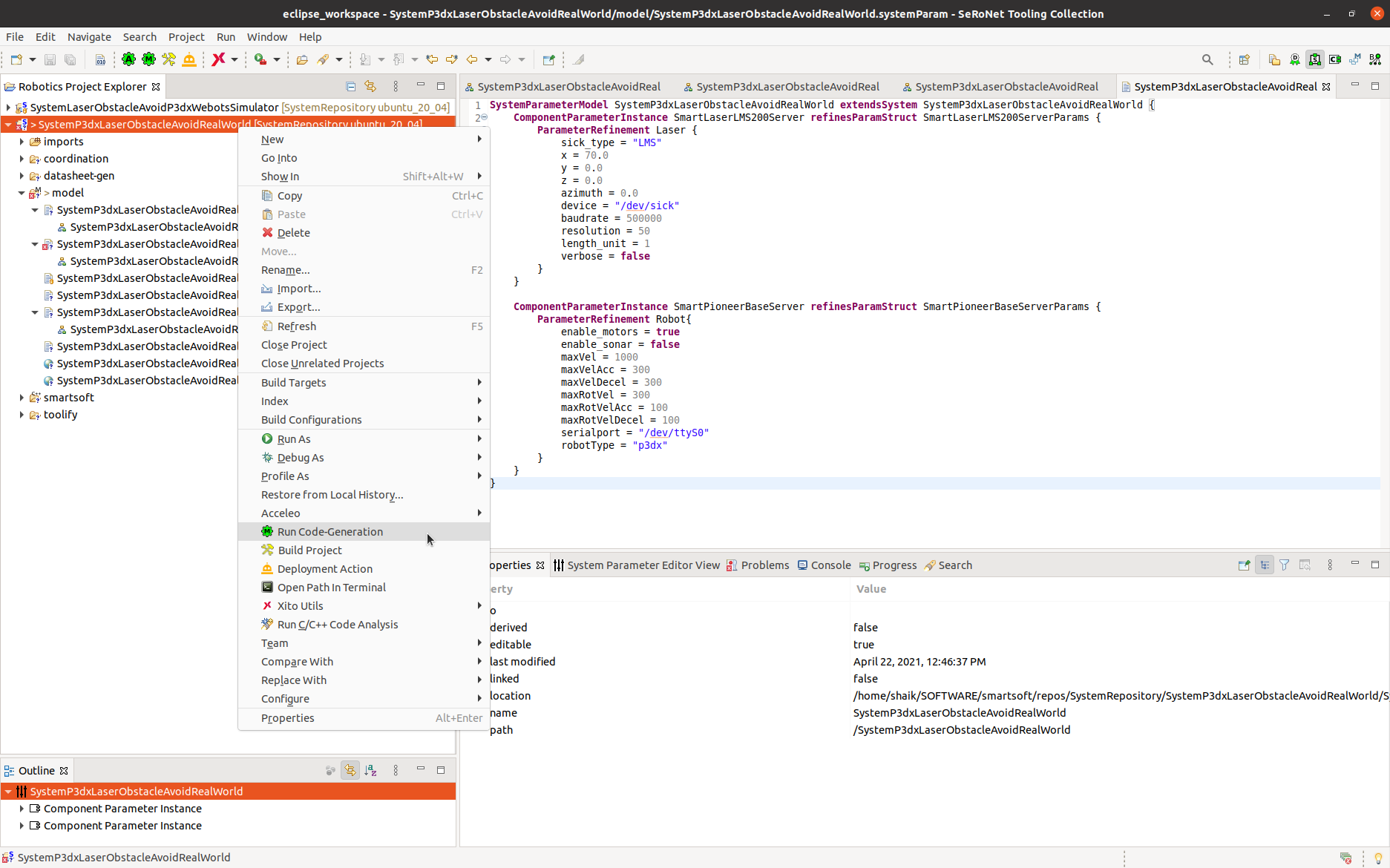
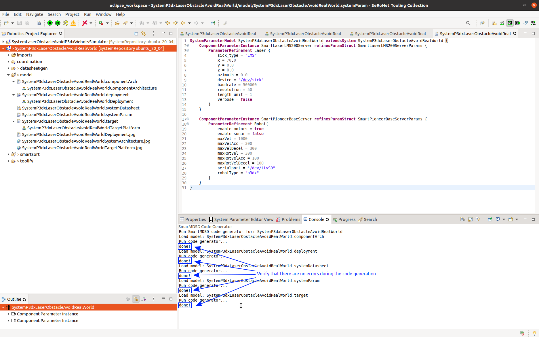
Step 6.a: Right click on the project → Run Code-Generation. This generates startup scripts and configuration files (used by the components during their initialization). It also generates the data folders where the components find required data.
Verify that there are no errors during the code generation by looking at the Console terminal:
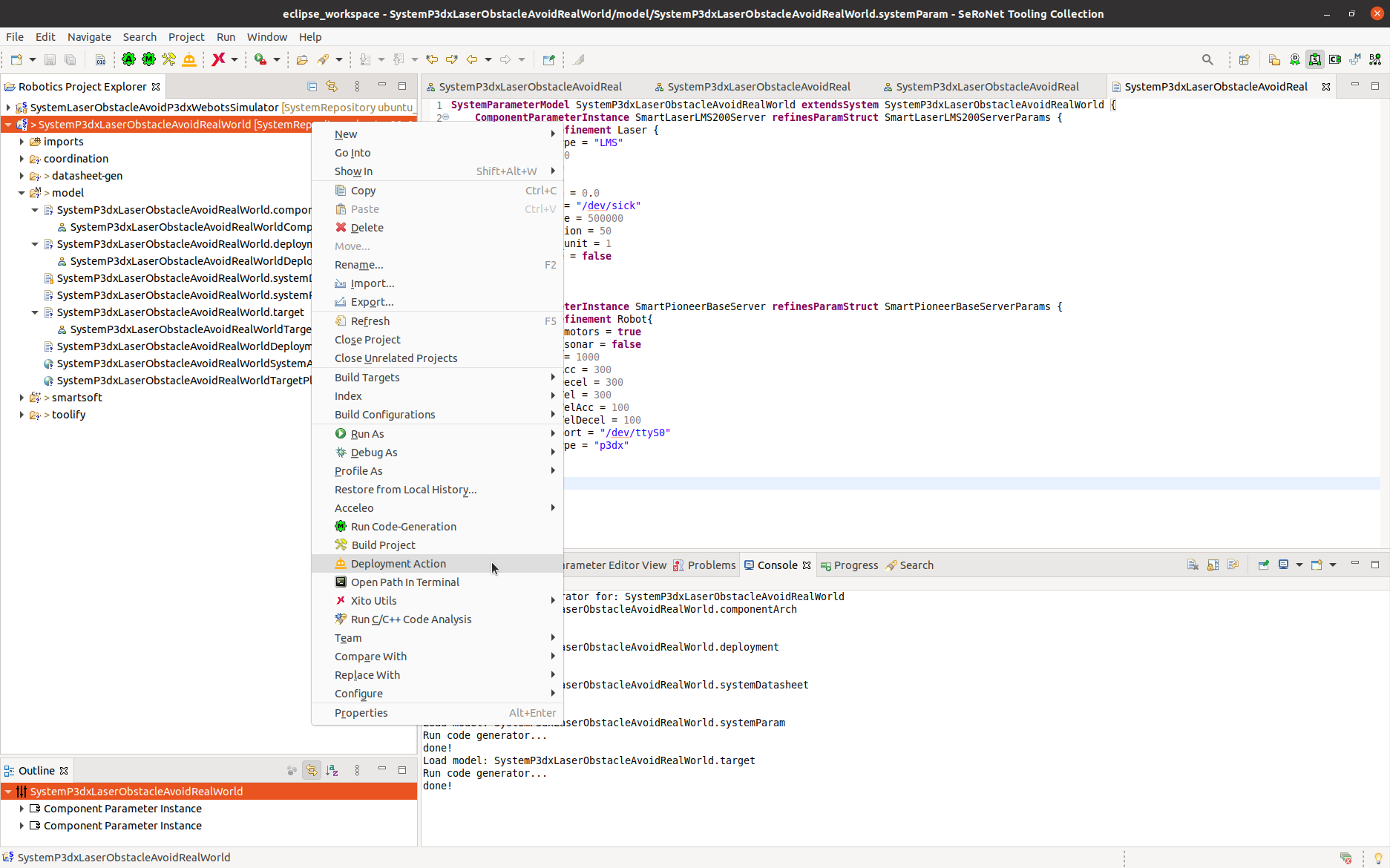
Step 6.b: We now deploy the system by clicking the Deployment Action from the right-click menu of the project:
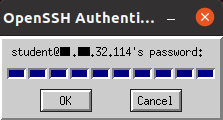
Step 6.c: You are now prompted for a password. We configured the system to use the login Student. for which the password is student. Just enter the password and the deployment gets completed. Password popup is prompted 2 times and you need to enter password each time.
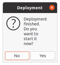
Step 6.d: Now a message box appears and asks whether you want to start execution. Answer No.
Execution
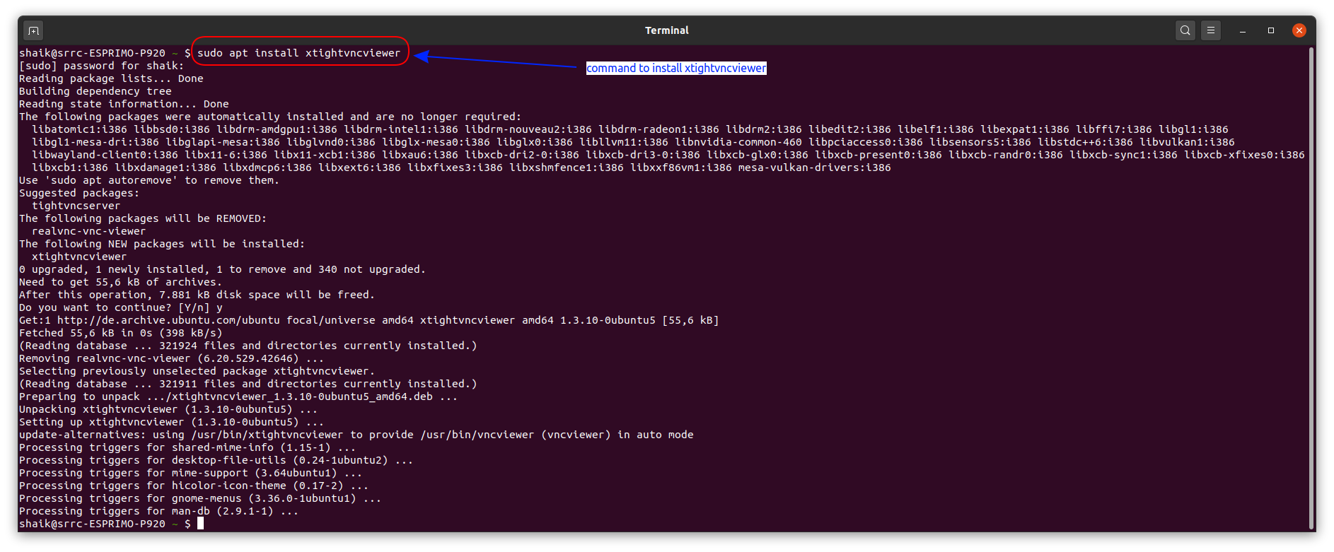
Step 7.a: Installation of the vncviewer in your PC for accessing the robot remotely:
  sudo apt-get install xtightvncviewer
  of course, you can also use any other suitable tool
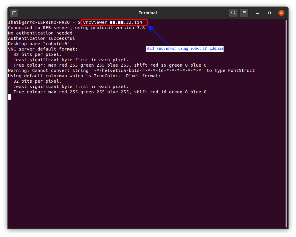
Step 7.b: Start vncviewer using robot IP address as shown.
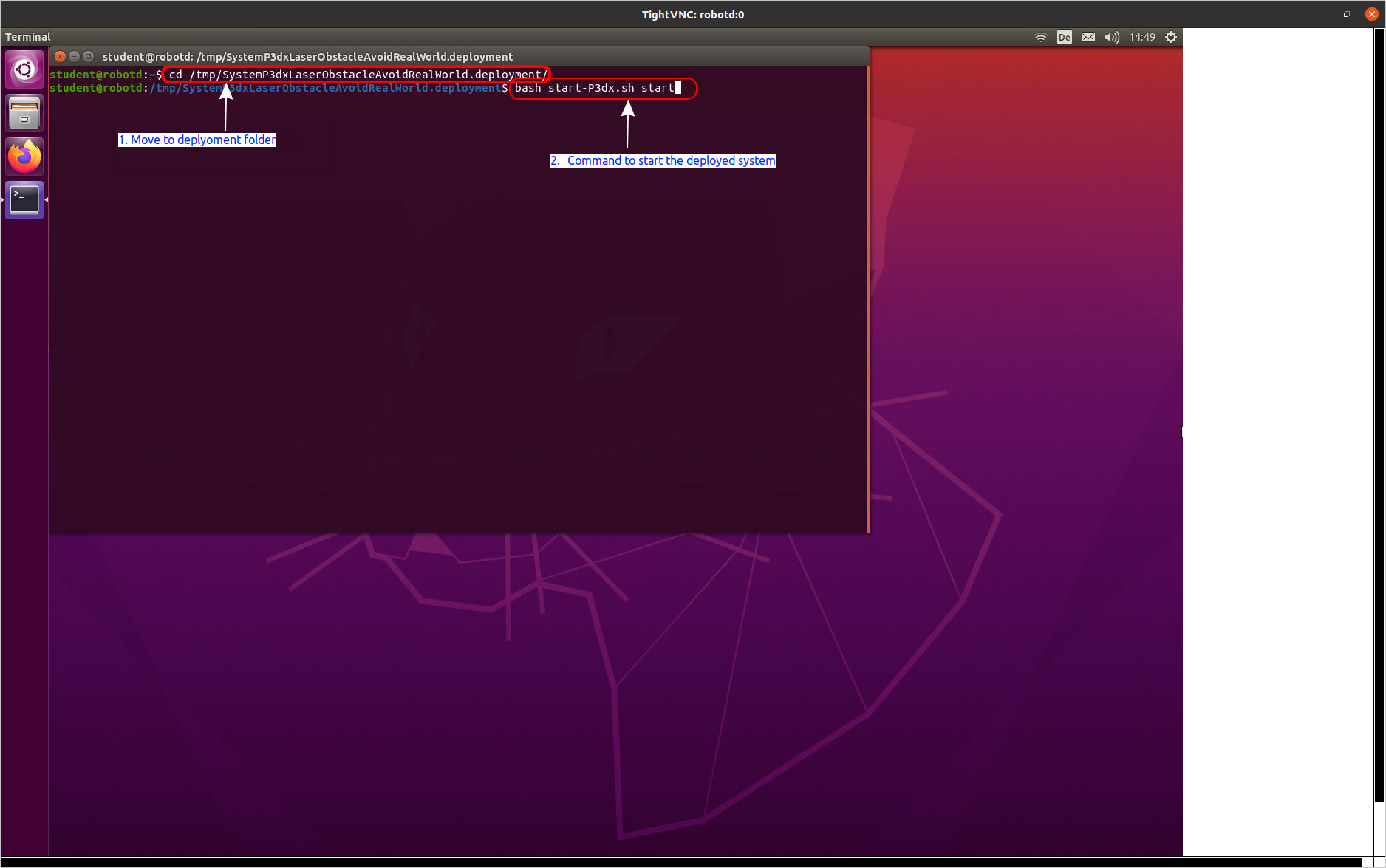
Step 7.c: Login to the robot using the account student with password student and then navigate to the specified deployment folder. The default folder is /tmp. In there you find a folder with the name of the system project. In this tutorial, we use SystemP3dxLaserObstacleAvoidRealWorld. Now you can start the system as shown below using the indicated shell script.
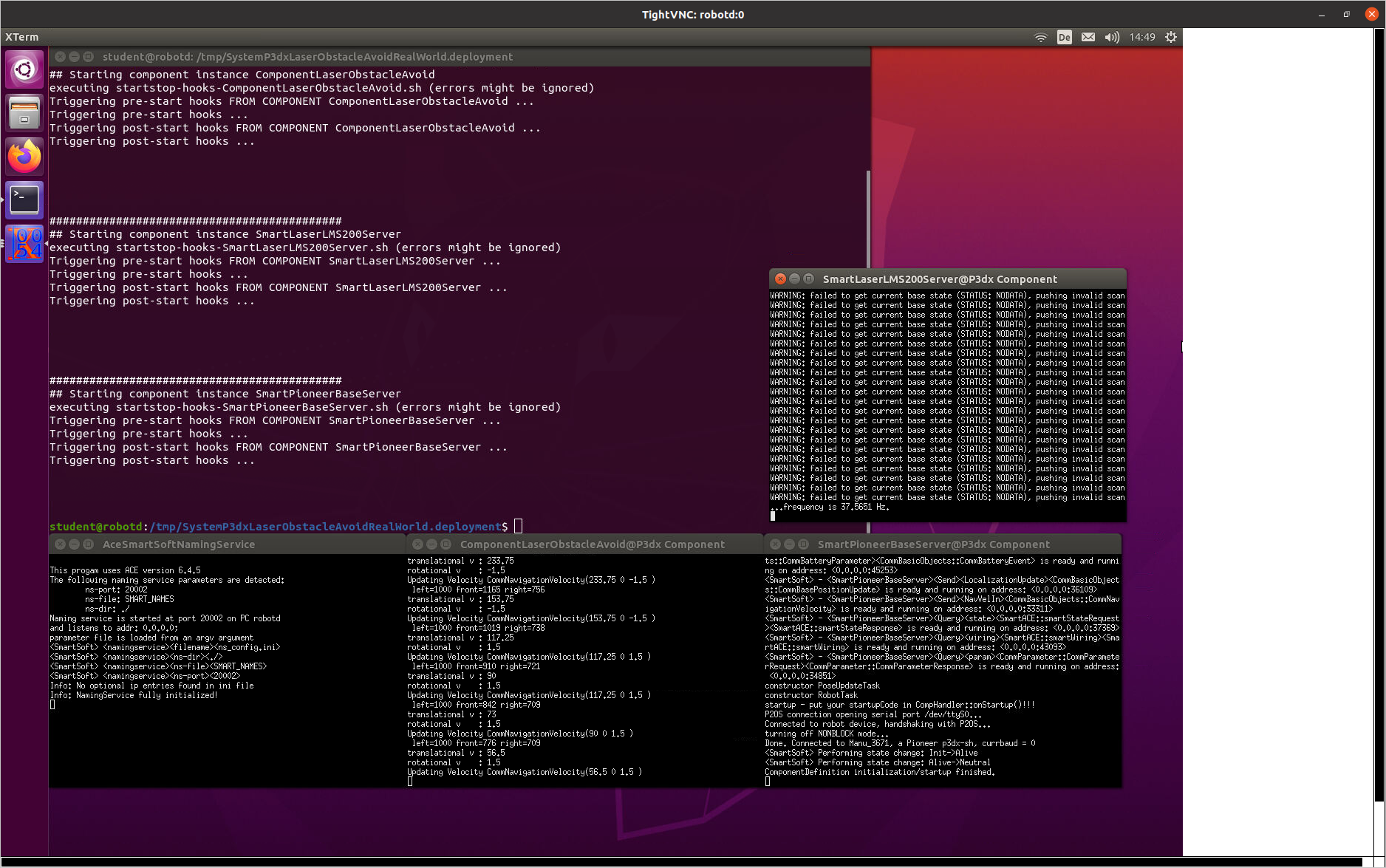
Now the system is running and you can observe that real robot is moving. And in the vncviewer you can check the terminals to see the output from components.
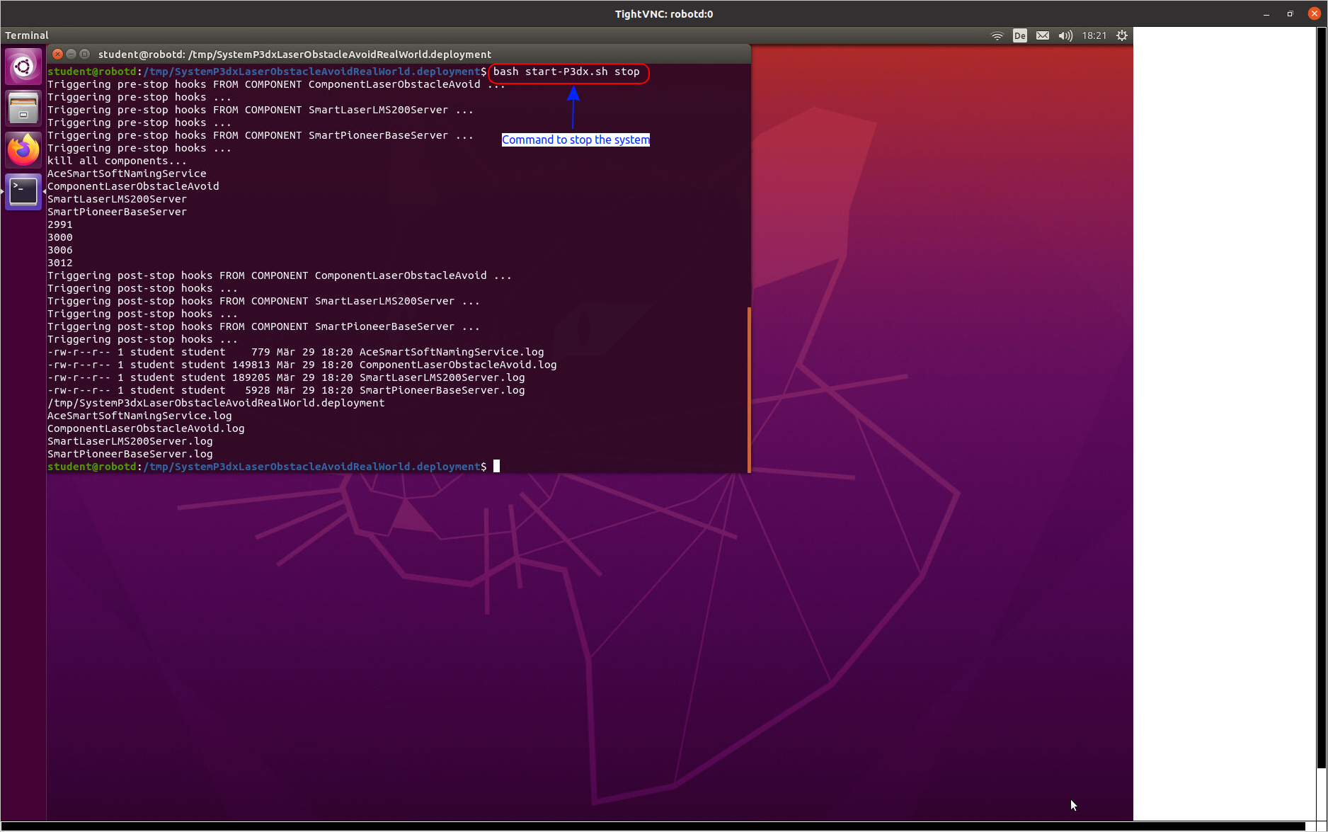
You can use the same shell script to stop the system (use stop instead of start as argument):
What to do next?
Now you can proceed with the tutorials in lesson Lesson 4: Flexible Navigation Stack - New Environments, Skills, and more

