Table of Contents
Student Exercises
This is a set of student lab work exercises which are used in different courses. As these lab exercises are embedded in courses, they have a different focus and a different order than the tutorials. The student lab work exercises supplement material and refer to the tutorials whereever reasonable.
Basic Information
| Level | Student |
|---|---|
| Role | We walk you through different roles |
| Assumptions | Background information from the related course |
| System Requirements | See the below section Preparation |
| You will learn | How to program robots, compose systems and run applications with a model-driven approach in simulation and in real-world |
Preparation
Typically, the software infrastructure is already setup in your lab. Talk to the lab staff and you get the credentials in the lab. Go ahead with the exercises.
In case you need to setup the software infrastructure on your own or in case you want to run the software on your own computer, please follow the instructions . There you find the instructions for downloading a ready-to-run virtual machine and also the link for a direct installation onto your PC without a virtual machine.
Exercises: Laser Ranger
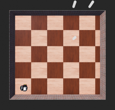
We use a simple laser-based obstacle avoidance algorithm with a simulator to make the first steps with the SmartMDSD toolchain. You then implement a laser-based hallway following algorithm, a laser-based wall-following algorithm, and finally a laser-based algorithm for detecting and approaching a cylinder.
Lab 1: Laser-Based Obstacle Avoidance
Your task is to figure out how the laser obstacle avoid algorithm works. Can you explain what is does?
You learn:
- how to start a ready-to-run system
- how a simple laser-based obstacle avoidance algorithm looks like
- how the internals of a component look like
- how to access the ports of a component from inside a component
- how to recompile a component in case you did modifications
Follow the tutorial Simple System: Laser Obstacle Avoid and use the following versions:
| Projects to use for this Exercise | Version |
|---|---|
| Component Project | ComponentLaserObstacleAvoid |
| System Project | SystemLaserObstacleAvoidP3dxWebotsSimulator |
The following gives some more information on the laser data communication object:
- look also at the documentation inside | CommMobileLaserScan.hh
- a laser scan is a collection of rays (or scan points i.e points in the laser scan)
- the resolution of a scan is the angle between consecutive rays
- a ray with zero angle aligns with the robot heading
- each scan point has a distance, an index, a reflectance (not used in simulators)
- the start angle, resolution, and index are used to determine the angle of the ray: angle of the ray = (start angle) + (resolution) * index
Eclipse Tips: How to find information about the domain models used in a component?
The domain models comprise the description of the services, that is communication patters along with communication objects. Communication objects comprise documentation of how to use them inside components.
- To see the definition of a class or a function, select it and press F3. This takes you to the definition of the class or function. Most functions in the domain models are documented.
- If a list of files is shown after pressing F3, select one of the files in the list. The same file can be shown multiple times because the same file occurs in the source directory as well as in the include directory.
- Press “Alt + left arrow” to go back to the previous file in the editor.
- Refer to this link for more Eclipse editor keyboard shortcuts.
Lab 2: Drive in the Middle of a Hallway
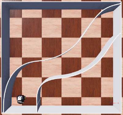
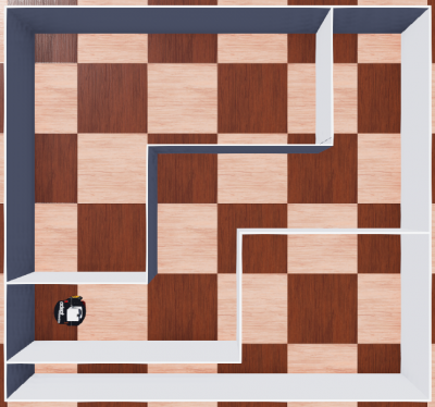
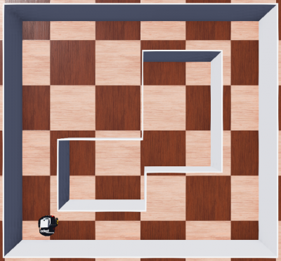
Your task is to let the robot move in the middle of the hallway. For this, use the laser ranger, calculate motion commands and command them to the robot. We provide two different worlds which come with different challenges for your algorithm.
- You get more familiar with the characteristics of a 2D laser ranger
- You gain more experience in modifying, compiling, deploying and running a system with the model-driven toolchain
| Projects to use for this Exercise | Version |
|---|---|
| Component Project | ComponentExerciseDriveMidway |
| System Project | SystemExerciseLaserDriveMidway |
Changing the World in a System Project
Step 1: To change the world used in the system project, you need to edit the *.systemParam file.
This file contains the parameters of the components used in the system. ComponentWebots uses the parameter WorldPath to load the webot's world. Change the value of the WorldPath to the path of the webots world file (i.e .wbt file).
Step 2: You must run the code generation after the modification. Right click on the project and select “Run Code-Generation”.
Step 3: Now you can deploy the system and you see the selected world loaded in the webots simulator.
Lab 3: Wall Following
Your task is to let the robot follow the left / right wall. For this, use the laser ranger, calculate motion commands and command them to the robot. Again, we provide two different worlds which come with different challenges for your algorithm.
| Projects to use for this Exercise | Version |
|---|---|
| Component Project | ComponentExerciseFollowWall |
| System Project | SystemExerciseLaserFollowWall |
Lab 4: Approach Cylinder
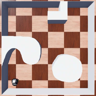
Your task is to let the robot approach a cylinder (move to a detected cylinder and stop in front of it). For this, use the laser ranger, calculate motion commands and command them to the robot.
- the diameter of each cylinder is 15cm
- there is a depth jump in the laser scan points at the left edge and the right edge of the cylinder. This can be used to detect a cylinder
- be aware, your algorithm should work still in case there are several cylinders in the scenario
| Projects to use for this Exercise | Version |
|---|---|
| Component Project | ComponentExerciseApproachCylinder |
| System Project | SystemExerciseLaserApproachCylinder |
How to Move a Cylinder in a Webots World?
- Step 1: Select the cylinder, after the selection you will see the coordinate system arrows of the cylinder.
- Step 2:
- Option 1: You can use the mouse to drag the arrows to move the cylinder.
- Option 2: Shift + hold the left mouse button and move the mouse to move the cylinder.
Exercises: RGBD-Sensor
We now use an Intel Realsense RGBD sensor instead of a laser ranger. A RGBD sensor provides a colour camera image (RGB) and a depth image (D).
See the User Guide for the Visualization Component for detailed information of how to visualize different data such as laser scans as well as camera and depth images etc.
Lab 1: Intel Realsense instead of Laser Ranger
This exercise shows how you can use a depth camera (in our example, an Intel Realsense RGBD camera) instead of a laser ranger. We illustrate the use of the depth camera by the example of the obstacle avoidance algorithm which so far used a laser ranger. We added another component which converts the 2-dimensional depth image from the RGBD camera into a laser scan.
We use the following fully preconfigured system: SystemExerciseRGBDObstacleAvoid.
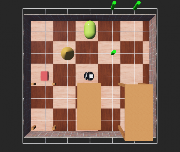
After starting this system, the robot moves around and avoids obstacles based on the depth image of the RGBD camera. The world used in this scenario is shown in the figure below.
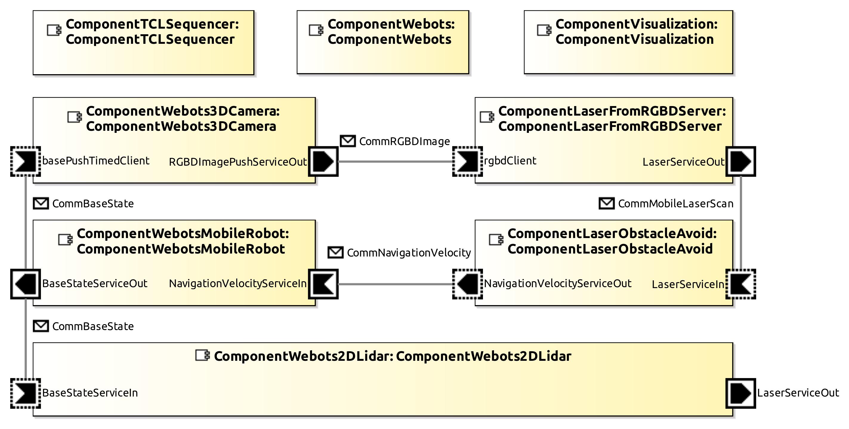
Please go to the System Builder perspective and see which components are used now and how they are wired:
ComponentWebots3DCameragenerates color and depth images (CommRGBDImage) and sends them toComponentLaserFromRGBDServerComponentLaserFromRGBDServerconverts the depth image into the laser data format (CommMobileLaserScan) and sends it toComponentLaserObstacleAvoid. Basically, the conversion is a down-projection of the depth image to result in a planar laser data format (all the scan points are in a horizontal plane)ComponentLaserObstacleAvoidcalculates velocity commands for collision free motions and sends those (CommNavigationVelocity) toComponentWebotsMobileRobotComponentWebotsMobileRobotdrives the mobile robot according to the given velocities
What are the take home messages from this exercise?
- Please notice that there is no connection anymore from
ComponentWebots2DLidartoComponentLaserObstacleAvoid. The laser ranger is not used anymore for obstacle avoidance. - While the laser ranger sees obstacles only in a horizontal plane, the depth camera has a different field of view which allows to detect more obstacles. For example, in the used world, the laser scanner is mounted too low to detect the table top while the depth camera is able to detect it and to avoid it.
- Press CTRL + F8 in Webots to show / hide the rays of the laser ranger and to check what part of the world it sees and which not
- Although we are now using a different sensor, we can reuse the laser obstacle avoidance component without any modifications at this component.
- of course, it just provides a port for receiving laser scans but we can connect any component that has a port for providing laser scans. For this, we just added another component in between the RGBD camera component and the laser obstacle component.
Lab 2: Approach Cylinder
For this exercise, we use the following versions:
| Projects to use for this Exercise | Version |
|---|---|
| Component Project | ComponentExerciseRGBDApproachCylinder |
| System Project | SystemExerciseRGBDApproachCylinder |
Similar to Exercises: Laser Ranger / Lab 4: Approach Cylinder, we now want to approach a cylinder. The difference is that we now use the RGBD camera:
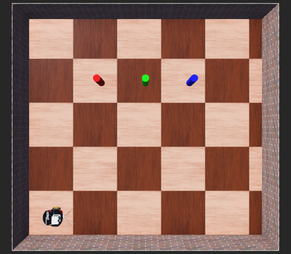
- detect a cylinder of a given color via the colour and / or depth image
- approach the cylinder and stop in front of it
The world used in this exercise is shown below:
Your task is to write the corresponding software:
- add your code in ComponentExerciseRGBDApproachCylinder/smartsoft/src/RobotTask.cc
- the library OpenCV 4'is available to process images
Exercises: Navigation (Mapping, Path Planning, Localization, SLAM)
The following labs dive deeper into navigation. We start with ready-to-run system projects that involve a whole bunch of software components related to different aspects of navigation.
«to be added»
Lab 1: Ready-to-Run Navigation Stack
This lab gives you insights into a ready-to-run navigation stack. The navigation stack comprises components for path planning, for map building, for motion control, for localization, for task coordination, and for world models. The objective is to first get an overview on navigation capabilities and gain some experience with navigation capabilities before we go into details.
Please follow A More Complex System using the Flexible Navigation Stack.
Lab 2
«to be added»
Exercises: Manipulation
«to be added»
What do do next?
This tutorial is not part of a series.
Acknowledgment
Contributions of Nayabrasul Shaik, Thomas Feldmeier.


