Table of Contents
Composing a System with OPC UA Mixed-Port Components
This tutorial builds on the tutorial Accessing an OPC UA Device: Using the Plain OPC UA Port (DeviceClient) to create a Mixed-Port Component, where a mixed port component has been developed. This tutorial will compose the mixed-port component together with other software components to a system.
- This tutorial is also available as video tutorial.
- See also this video demo: The effortless use of OPC UA enabled devices with software components.
Basic Information
| Level | Advanced |
|---|---|
| Role | System Builder |
| Assumptions | This tutorial assumes you know how to compose components in a system (see Develop Your First System by Composing Software Components), and that you have a basic understanding of OPC UA. |
| System Requirements | - Software components “ComponentJoystickServer”, “SmartJoystickNavigation” , and “SmartGazeboBaseServer” - The OPC UA enabled Joystick “OPCUAJoystickDevice” - Gazebo simulation emvironment. - We assume you have completed Accessing an OPC UA Device: Using the Plain OPC UA Port (DeviceClient) to create a Mixed-Port Component. |
| You will learn | How to use a Mixed-Port Component with a Plain OPC UA Port (DeviceClient) in a system |
Introduction
This tutorial will step by step develop a system composed from two mixed-port components (on the left and on the right of the figure) and one regular component (in the middle of the figure):
The mixed-port component named “ComponentJoystickServer” (on the left in the figure) interacts with a regular, external OPC UA server to periodically receive joystick values (i.e. buttons, axes, etc), and provides these joystick values as a “JoystickService” to the second component named “SmartJoystickNavigation”. This second component receives the joystick values at its “JoystickServiceIn” port, transforms the values into a navigation command (i.e. translation and orientation velocities), and publishes this command at the component port named “NavVelServiceOut”. The last component named “SmartGazeboBaseServer” (on the right of the figure) periodically receives navigation commands, and propagates them to a Gazebo-based simulation environment that has a mobile robot which understands and executes these navigation commands.
This tutorial consists of two parts:
- First, components will be composed to a new system.
- Second, this system will be deployed and executed.
Note on Preconditions
As a precondition of this tutorial, we assume that you are either using the Virtual Image (with preinstalled SmartSoft environment + Gazebo simulator), or that you have manually installed a SmartSoft environment on your development PC.
The relevant components for this system can be found in the Component Repository. If you prefer to browse the final result of this tutorial: The system created in this tutorial can also be found in the system repository.
The “ComponentJoystickServer” component of this scenario requires an external OPC UA server named “OPCUAJoystickDevice”, that can be downloaded here: OPCUAJoystickDevice. To compile it on your development PC, at least the “open62541” library needs to be installed on your development PC. Please follow the specific installation instructions.
Finally, the component named “SmartGazeboBaseServer” of this scenario requires a preinstalled “Gazebo 8” simulation environment; see installation instructions of the software component.
Composing the System
Composing the system with mixed-port components is alike composing a system with common ports. The difference lies in the suppression of plain OPC UA ports as possible candidates for the inter-component connection. Please see the following tutorial “Develop Your First System by Composing Software Components” for details on composing a system in general.
Open the System Builder (Tier 3) perspective
Forst we have to open the System Builder (Tier 3) perspective (available since toolchain version 3.9) as explained in the basic tutorials.
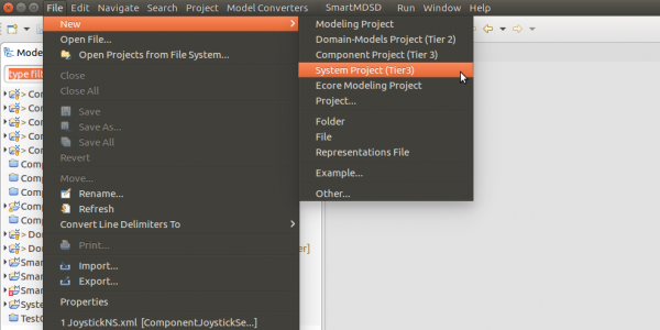
Create a new system project (Tier 3)
Compose the system component architecture
Compose the system component architecture model as described in Develop Your First System by Composing Software Components. The result shall look like the screenshot below.
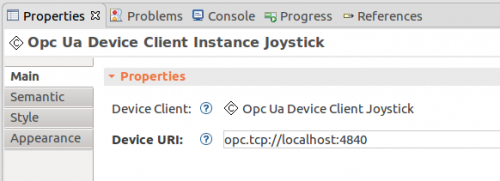
Optinally, the device URI for the plain OPC UA Joystick port of the “ComponentJoystickServer” can be adjusted by selecting the Joystick element in the system diagram and opening the Properties view. In case if the properties view is not visible in you Eclipse instance, you can open it again using the menu: “Window” → “Show View” → “Properties”. If you start the “OPCUAJoystickDevice” at the same target as the overall system, then this URI can keep the default value. Otherwise, use the respective address of the target where the “OPCUAJoystickDevice” is actually executed.
Create target platform “Laptop”
Create a target platform model as described in Develop Your First System by Composing Software Components. The result shall look like the screenshot below. For simplification, we recommend to deploy to your local system.
Develop deployment schema
Create a deployment model as described in Develop Your First System by Composing Software Components. The result shall look like the screenshot below.
Deploying and Executing the System
In this section, we demonstrate how a system is deployed to and executed in a target environment. The general steps are the same as in the dedicated deployment tutorial Develop Your First System by Composing Software Components. The only difference is that we have to launch the OPC UA Joystick Device between deployment and execution.
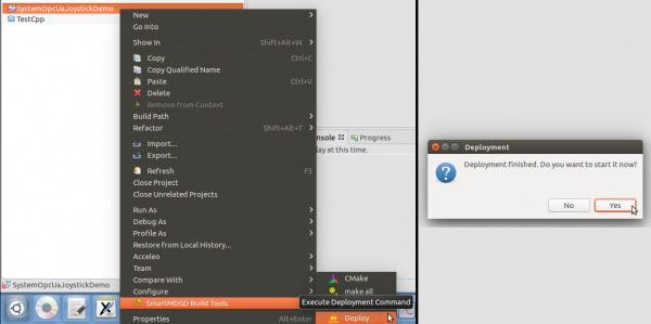
To deploy a system, you can right-click on the system project, expand the submenu SmartMDSD, and select the Deploy command.
The deployment command will copy all the precompiled binaries and libraries, as well as all the required configuration files and start-up scripts to the designated remote location, which in our case the folder “/tmp” at localhost. Please note that the deployment command uses SSH copy and thus may require to enter the password in case you do not have your ssh key installed.
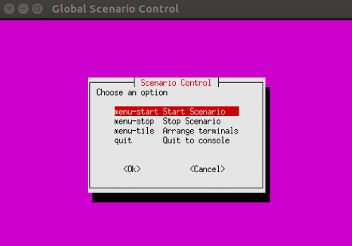
After the deployment action finishes, a popup dialog will appear asking whether the deployed system should also be started. Confirming to do so by clicking on “yes” will open a new console window:
At this point we would normally select the “Start Scenario” menu option, however, for our specific scenario we first need to execute the “OPCUAJoystickDevice” manually as this program is not part of our system (i.e. it is assumed to be running for our system). As we also provide the OPC UA server by ourself. We will first start it manually as follows.
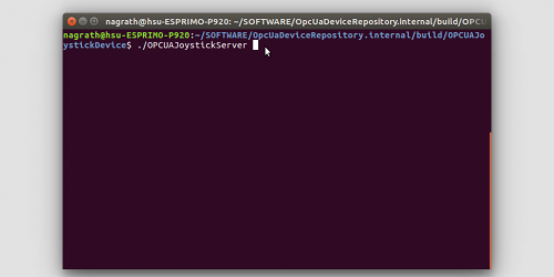
In a new console window, locate and execute the OPCUAJoystickDevice server.
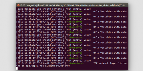
The OPCUAJoystickDevice server will internally initialize a linux joystick device driver using “/dev/input/js0” as the default device location, and start a new OPC UA server that listens on the address "opc.tcp://localhost:4840".
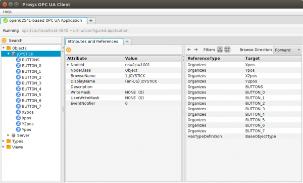
Optionally, we can check if the server is running correctly using the Prosys OPC UA Client for example.
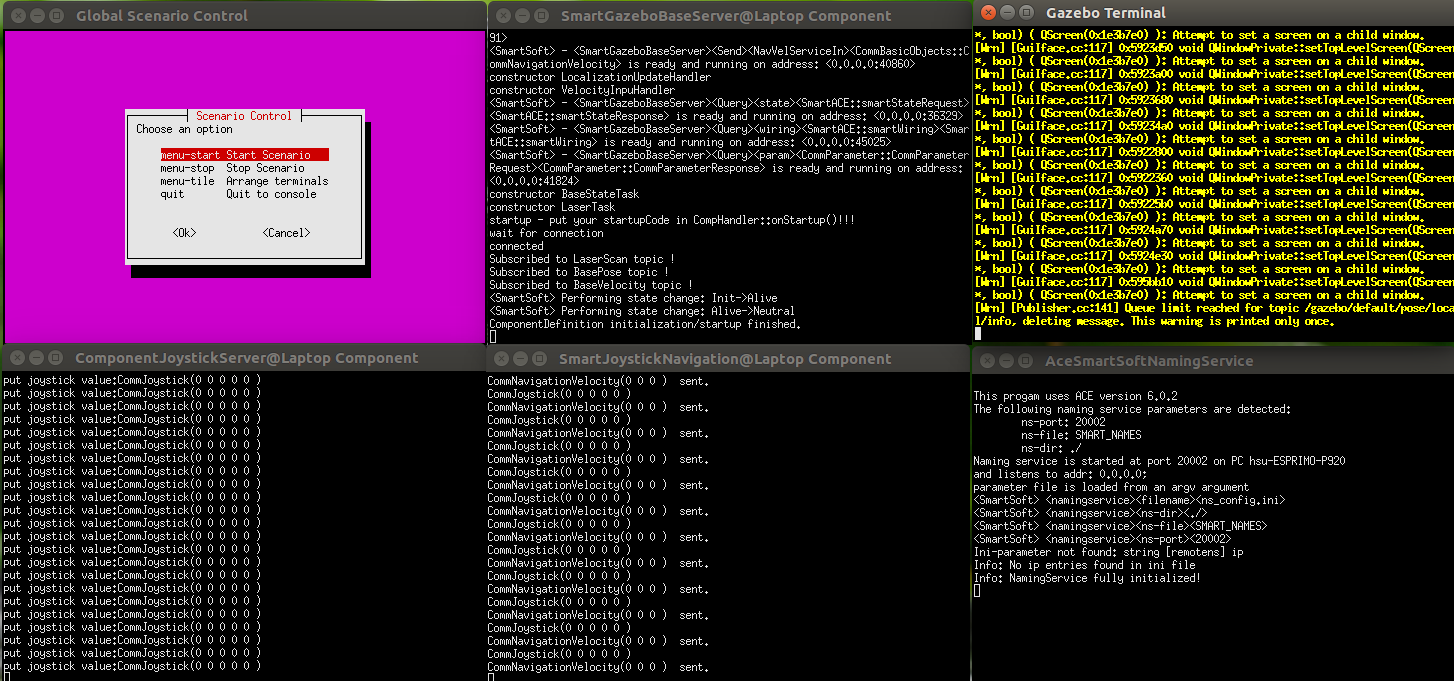
We will now start the composed system by triggering the “Start Scenario” menu option within the console menu. This will execute a naming service, the three components of our system, and the Gazebo simulation environment.
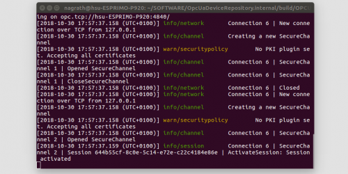
In our prevoisly started OPCUAJoystickDevice console we can observe that the OPC UA server has accepted a new client connection.
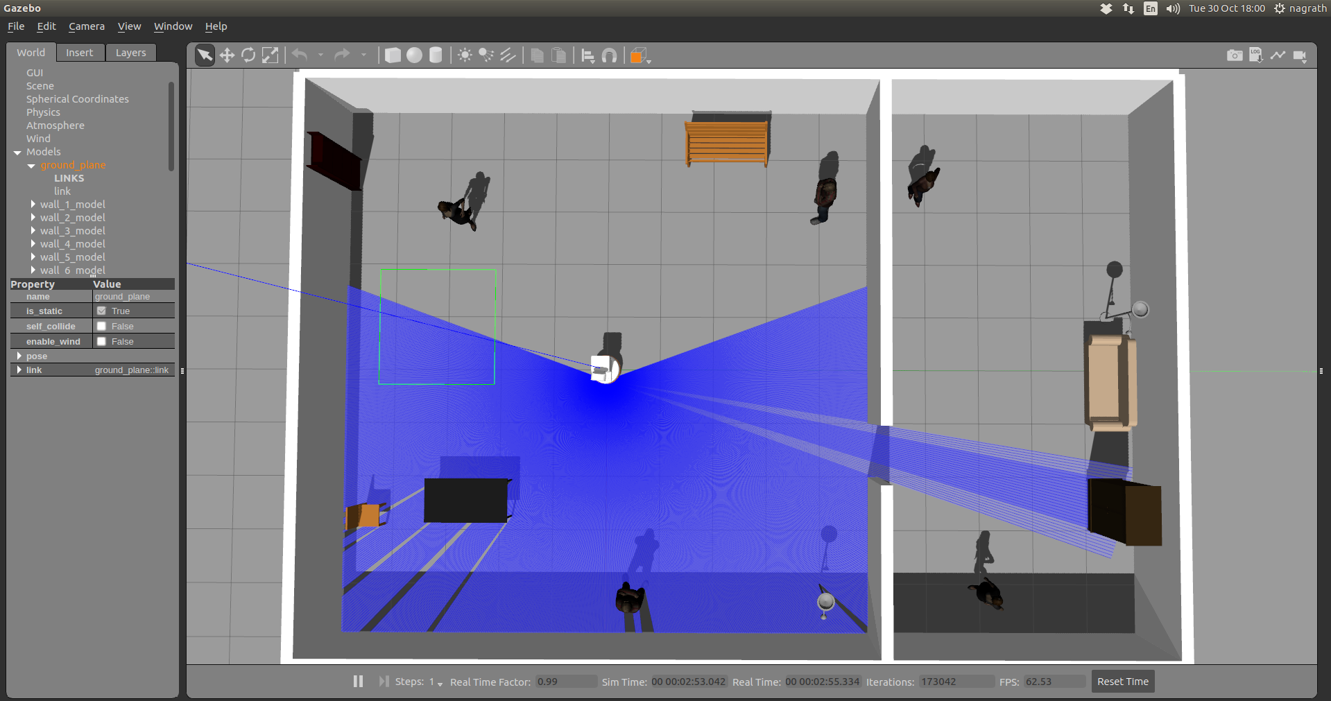
In addition to the components of the system, also a Gazebo-based simulation environment is automatically started. Moreover, Gazebo should automatically load an office envoronment and initialize a PAL Tiago Robot.
You can now move the robot around using the joystick.
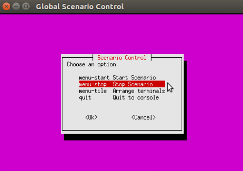
To stop the running scenario, select “Stop scenario” in the console menu and press enter.
Further Information
- The OPC UA Joystick Device (OPCUAJoystickDevice) is part of the OPC UA Device Repository
- System Composition: System Component Architecture
What do do next?
The next tutorial in the OPC UA series shows how to develop a mixed-port component with an Plain OPC UA Server Port (ReadServer).


