Table of Contents
Accessing an OPC UA Device: Using the Plain OPC UA Port (DeviceClient) to create a Mixed-Port Component
This tutorial describes how component supplier models a mixed port software component with a plain OPC-UA port to communicate with a OPC UA enabled devices.
This tutorial is also available as video tutorial [Outdated Video: Refer text tutorial].
Basic Information
| Level | advanced |
|---|---|
| Role | Component Supplier |
| Assumptions | You know how to model software components in general and how to implement business logic in general (see Develop Your First Software Component). You have a basic understanding of OPC UA. |
| System Requirements | Open62541CppWrapper (use specific installation instructions) |
| You will learn | - How to model a mixed-port software component with a Plain OPC UA Port (DeviceClient) - How to implement the business logic using the generic OPC UA infrastructure - How to add the XML information model to the port and implement the business logic using the device-specific OPC UA infrastructure - How to use the OPCUAJoystickDevice, an OPC UA enabled joystick driver |
Introduction
The reader will learn a step-by-step walkthrough on modeling a mixed-port software component, adding activities to that component and implementing component's intended business logic. The business logic can either be implemented using the generic OPC-UA infrastructure or by importing server's information model through an XML file.
The XML file is encoded according to OPC-UA nodeset schema and describes a server's nodeset (Methods and variables). The compiler generated code provides a device-specific OPC-UA infrastructure using the XML nodeset file, which can be used to implement component's business logic.
This tutorial is structured as follows:
- How to model a software component with a Plain OPC UA Port (DeviceClient)
- How to implement the business logic using the generic OPC UA API
- How to add the XML information model to the OPC UA Port (DeviceClient) and how to implement the business logic using the device-specific OPC UA API
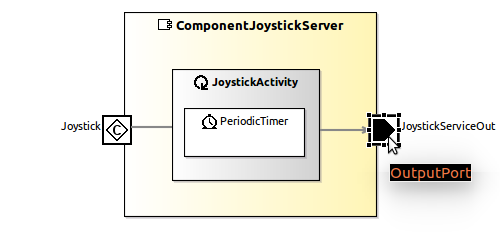
This tutorial will step by step describe how to develop the following mixed-port component:
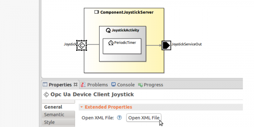
The figure above shows a so-called Mixed-Port Component that has a plain OPC UA Port (DeviceClient) on the left (see the port named “Joystick”) to communicate with traditional OPC UA devices and a regular Component Communication Port on the right (see the port named “JoystickServiceOut”) that utilizes service-oriented communication via Communication Patterns. The plain OPC UA Port (DeviceClient) internally implements an OPC UA client that connects to a remote OPC UA Server that provides the Joystick values (including the button states) over a regular OPC UA interface. The “JoystickActivity” within the “ComponentJoystickServer” accesses the plain OPC UA Port (DeviceClient) to get the current Joystick values, transforms these values into a Joystick Communication Object, and pushes this Communication Object to the “JoystickServiceOut” port. In this way, this component effectively bridges between the plain OPC UA world and modeled systems consisting of various software components.
This “joystick” port of the software component will connect to a OPC UA enabled joystick device (get it here: OPCUAJoystickDevice). The next tutorial will provide more information how to use the joystick device.
The mixed-port component developed here can also be found in the component repository.
Modeling: Software component with a Plain OPC UA Port
Open the Component Supplier (Tier 3) perspective
First, we have to open the Component Supplier (Tier 3) perspective (available since toolchain version 3.9) as explained in the basic tutorials.
Creating a new component project and enabling SeRoNet tools
In this section, a new component is created and the specific view is activated that enables the modeling of plain OPC UA Ports.
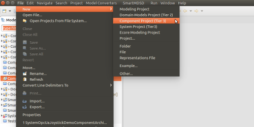
The first step is to initiate a new component project (Tier 3). Therefore, we use the related Project Creation wizard:
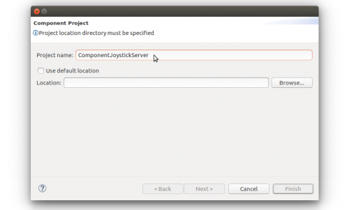
In the next window of the wizard, we provide a name “ComponentJoystickServer” for the component project. Optionally, we can also specify a custom location for the component project on the hard-disk. By default, the wizard creates a subfolder named as the component name within the workspace folder.
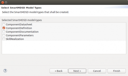
If we click on the “Next” button we will be taken to dialogue to select the model types.
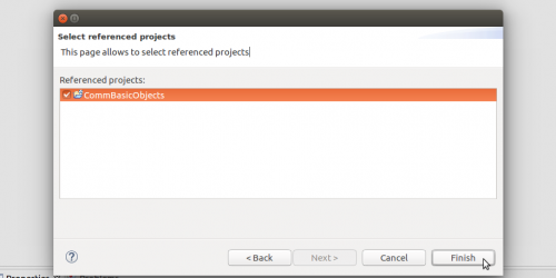
After this step, we may click on the “Finish” button to skip further dialogues and start with the default services. We may click “Next” to select which services we want to realize in this component. Services are defined in a separate project by a separate role. For our component, we select the “CommBasicObjects” Domain Models (Tier 2).
Please note, that each Domain Models (Tier 2) repository consists of multiple definitions for Communication Objects and for Service Definitions. Further below, we will select one of the services from this selected repository to be realized in our component.
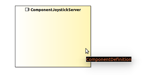
After pressing “Finish”, the wizard will create a new project in the current eclipse workspace and will generate an empty component model. In the end, the wizard opens the newly generated ComponentDefinition model in the ComponentDefinition diagram.
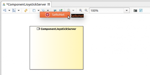
Now, we can start adding component-specific model elements, like component ports and component activities. Optionally, enable the SeRoNet extensions:
The selection of the SeRoNet view activates an additional modeling layer in the ComponentDefinition diagram, which among others activates the SeRoNet tools in the tools palette.
In the next section, we will complete the component model by adding further model-elements, in this case, a Plain OPC UA DeviceClient Port, an OutputPort and an Activity.
Creating Activities, establishing input and output ports
In this section, we will add the plain OPC UA DeviceClient port, add a new Activity element, and add an Output port.
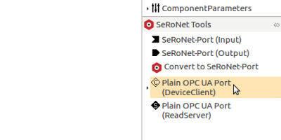
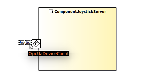
First, we add a plain OPC UA DeviceClient port, therefore, select the “Plain OPC-UA Port (DeviceClient)” tool in the SeRoNet tools palette and attach the port to the component's rectangle border. Now name the plain OPC-UA port as “Joystick”.
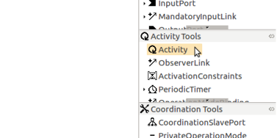
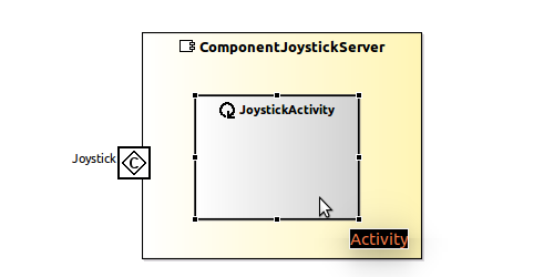
Next, we will add a new Activity to the component. To do so, select the “Activity” tool in the activity tools palette and drag and drop a new activity element onto the component. Name the activity “JoystickActivity”.
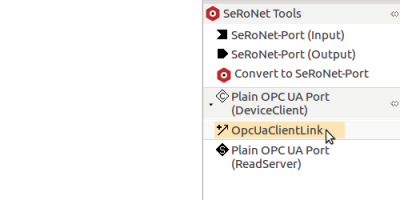
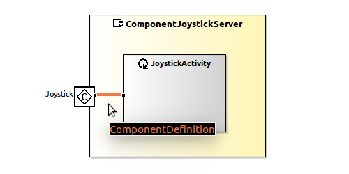
Next, we will link the new Activity with the OPC-UA port that we have modeled above. To do so, select “OpcUaClientLink” tool in the SeRoNet tools palette (please note that to see this tool you need to expand the submenu of the “Plain OPC UA (DeviceClient)” tool). You can make a link by first clicking on the plain OPC-UA port “Joystick”, and second clicking on the activity “JoystickActivity”.
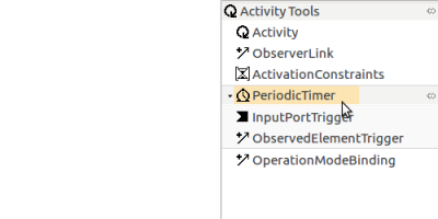
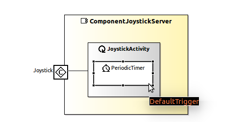
We can specify different types of triggers for an activity (like an input-data-based trigger, or a timer-based trigger). In this example, we use a PeriodicTimer as a trigger. Select the “PeriodicTimer” tool in the activity tools palette and drag and drop a new periodic timer onto the activity “JoystickActivity”.
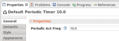
The update-frequency ot the periodic timer can be changed in the Properties tab. In our example, we specify the update-frequency of 10 Hz. Just in case if the properties tab is closed in your Eclipse instance, you can open it again using the menu: “Window” → “Show View” → “Properties”.
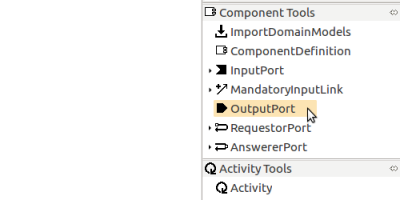
As a final modeling element in this tutorial, we will add an OutputPort. Select the “OututPort” tool in the component tools palette and attach it to the component border.
In contrast to the previous elements, an OutputPort requires further information about the other elements of the model, in this case, a selection of a ServiceDefinition and a selection of an Activity.
Fortunately, the modeling editor supports in defining a valid model by directly asking for the required model elements in the following popup windows that appear automatically after creating an OutputPort.
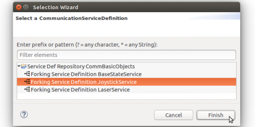
In the first popup window, select the appropriate communication service definition for the new output port.
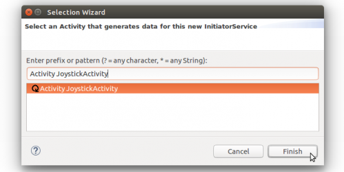
Selecting a ServiceDefinition means that this component will realize this definition. In the next popup window, we will select a required Activity, in this example, this is the “JoystickActivity”.
Selecting an activity is mandatory, as the selected activity will generate the data for our output-port. A component can define multiple activities and multiple output ports, and each output-port must be associated with exactly one activity, while an activity can operate several output-ports. After selecting the required model elements, the new output-port will be created and the required model element references will be automatically configured.
Please note, that the initially selected elements from the popup windows can be changed afterward without deleting and recreating the same element. As a final result, the component-definition model for our example should look like this:
We can initiate code generation by clicking on the “RunCodeGeneration” button or alternatively toggle on the “AutoCodeGeneration” button to regenerate the code on every change event.


In the next section, we will provide the C++ business logic to our component.
Implementing Business Logic using the Generic Infrastructure
In this section, we will learn how the generated C++ code infrastructure of our example component can be refined to add a component-specific business logic. The C++ code infrastrure is automatically generated and updated each time the model is changed and saved. For our example, the C++ code is generated into the following two subfolders that will be automatically created in our component project:
- plainOpcUa
- smartsoft
The first folder “plainOpcUa” contains an additonal subfolder named “src-gen” that contains autogenerated C++ code for our modelled plain OPC UA DeviceClient port. The C++ code in this folder should not be changed manually, as it will be regenerated each time the model is adjusted and saved (all the manual changes in the code will then be overridden).
The second folder “smartsoft” contins two further subfolders “src-gen” and “src”. Again, the code within “src-gen” should not be changed manually, as all the manual changes will be overwritten when the code generated is triggered next time. By contrast, the code within the “src” subfolder is supposed to be refined by the user. The code generator only generates skeletons (i.e. C++ classes with empty implementations) that are supposed to be filled with further business logic code.
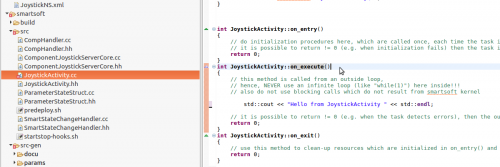
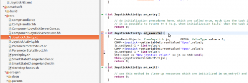
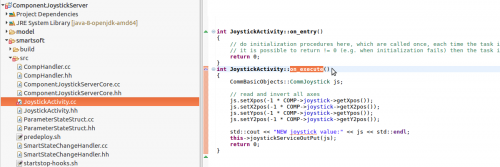
In our example, we will provide custom business logic for the “JoystickActivity”. This business logic in our example basically consists of converting the incoming data from the plain OPC UA DeviceClient port named “Joystick” into a “CommJoystick” communication object which will be handed over to the “JoystickServiceOut” output port to be published to all components that will be connected lated in a system. Therefore, we first expand the subfolder “smartsoft”, in there the subfolder “src”. Here we open the file “smartsoft/src/JoystickActivity.cc”, and locate the method “JoystickActivity::on_execute()“.
Now, we will provide an implementation for the “on_execute” method which will use the generic OPC UA API from our plain OPC UA DeviceClient port named “Joystick”. This API provides methods such as “callMethod(…)“, “setVariableValue(…)“, “getVariableCurrentValue(…)“, and “getVariableNextValue(…)“. In our example, we use the “getVariableCurrentValue(…)“ method to access the current incoming values, and to convert these values into a “CommJoystick” communication object. After creating and filling the communication object, we hand it over to the “JoystickServiceOut” output port (see last line before the return statement of the “on_execute()” method in the figure below).
This completes the development of our example component in this tutorial. The only remaining step is to build the component. To do so, select our component project in the Model Explorer and then trigger the Build Project button in the SmartMDSD menu. Note: in order to build the software component, we need the Open62541CppWrapper library installed (see section Basic Information).
In this section, we have used the generic OPC UA API of our plain OPC UA port. In the next section we will demonstrate the usage of a specific API that can be optionally generated based on a provided OPC UA information model.
Extending the model with an OPC UA Information Model
In the previous section we have used the generic OPC UA API for implementing the business logic. In this section we will use an existing OPC UA Information Model for generating a specific API, and we will use this generated specific API to respectively refine our business logic.
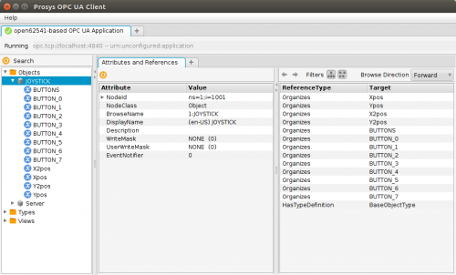
Here we assume that a regular OPC UA server is executed and that we have a network access (from our current development PC) to this server. The next image illustrates the information model for the OPC UA server. We use the Prosys OPC-UA client to view server nodes.
For our example, the information model consists of several OPC UA variables for the different buttons and joystick axes of the joystick device. All these variables are clustered within the OPC UA object named “Joystick”.
We assume that the OPC UA Information Model of the Joystick OPC UA server has been exported into an XML format conforming to the OPC UA Nodeset schema definition.
Importing server's OPC-UA nodeset schema
In this section, we will copy the OPC UA Information Model XML file (that is shown in the previous section) into our component project, and we will specify the information model file within our component model.
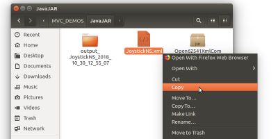
Get the required OPC UA Information Model JoystickNS.xml that comes with the OPC UA Joystick device.
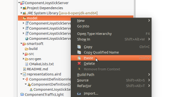
Copy and paste the XML file into the “model” folder of the component project.
Next, select the plain OPC-UA port named “Joystick” in the component diagram, open the Properties tab, and click on “Open XML File” button.
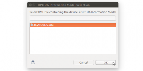
Select the XML file (the dialogue box will list all XML files present in the “model” folder).
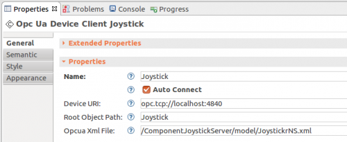
The selected XML OPC-UA nodeset file is now associated with the plain OPC UA DeviceClient port named “Joystick”. In the properties section, we may specify the proper root object path for the server. By default, this path is set to “Server” which equates to an absolute path “Objects/Server”. We may edit this path to reach the relevant root node “Server/…/ServerName” (Absolute: “Objects/Server/…/ServerName” ). In the current example, the root object node “Joystick” is directly under the “Objects” node hence root object path is set to “Joystick”.
Implementing Business Logic using device specific Infrastructure
Locate “JoystickActivity::on_execute()“ method in file “smartsoft/src/JoystickActivity.cc” and implementing business logic using device specific methods. Thanks to the XML definition, the tooling generates an joystick specific OPC UA instrastructure with device-specific methods such as getXpos(), getYpos(), and others to access the values of the OPC UA variables.
After refining the business logic, we rebuild the component project.
Further Information
- The OPC UA Joystick Device (OPCUAJoystickDevice) is part of the OPC UA Device Repository
What do do next?
The next tutorial will show how to compose a system using the mixed port component: Composing a System with OPC UA Mixed-Port Components


