Table of Contents
Developing an OPC UA Server: Using the Plain OPC UA Port (ReadServer)
This tutorial shows how to develop a mixed-port component with an Plain OPC UA Server Port (ReadServer). Plain OPC UA Server Port (ReadServer) allows mirroring data from a regular component service in an automatically generated OPC UA Server, thus allowing to access a component's data for traditional OPC UA clients via an OPC UA interface.
This tutorial is also available as video tutorial
Basic Information
| Level | Advanced |
|---|---|
| Role | - Component Supplier - System Builder |
| Assumptions | - You know how to model software components in general and how to implement business logic in general (see Develop Your First Software Component). - You know how to compose components in a system (see Develop Your First System by Composing Software Components). - You have a basic understanding of OPC UA and know the OPC UA client tutorials (mixed-port component and system) |
| System Requirements | - Open62541 library (use specific installation instructions) - SmartMDSD Toolchain 3.8 |
| You will learn | - How to model a software component with a Plain OPC UA Server (Read Server) - How to compose a system that consists of a component with a Plain OPC UA Server (Read Server). |
Introduction
This tutorial shows how a component supplier develops OPC UA Mixed Port Component with a Plain OPC UA Port (Read Server) to provide data to traditional OPC UA interface that mirrors internal data of a provided service. A mixed-port component serves as a bridge between OPC UA programs and RobMoSys-conformant components.
This tutorial explains all necessary steps to reproduce this task using the SmartMDSD Toolchain, an Integrated Development Environment for system composition in a robotics software ecosystem.
This tutorial is the counterpart of the previous OPC UA video tutorial: The previous one showed how to create a OPC UA Device Client to access OPC UA from within the software components (and how to use it in a system). By contrast, this video demonstrates how to have software components accessible from OPC UA with the help of Plain OPC UA Port (Read Server).
Scenario
The concept of Mixed Port Components is illustrated by a mobile robot that is moved via a joystick. The below figure shows the use-case for which this tutorial will develop the mixed-port component.
The mixed-port component named “SmartJoystickServer” (on the left in the figure) interacts with a joystick device (internally using the standard Linux joystick driver) and provides joystick values as a “JoystickService” to the second component named “SmartJoystickNavigation”. This second component receives the joystick values at its “JoystickServiceIn” port, transforms the values into a navigation command (i.e. translation and orientation velocities), and publishes this command at the component port named “NavVelServiceOut”.
The OPC UA use-case is that we want to access the navigation commands not only via the communication patterns, but also via OPC UA. For this purpose, the video shows how to add an OPC UA Read server such that the data provided at the “NavVelServiceOut” service is also provided via OPC UA. We will show this by viewing to the OPC UA Read Server via the Prosys client.
This tutorial consists of five parts:
- At first we explain the structure of an existing system and the component to which we will append a plain OPC UA Server (Read Server).
- We step by step explain the process of appending a plain OPC UA Read Server to component and system models.
- The updated system will be deployed and executed.
- We will connect to the plain OPC UA Read Server using a generic OPC UA client.
- We can now examine updates generated by the SmartJoystickNavigation component using a traditional OPC UA client while the scenario continues in the background.
Requirements
As a precondition of this tutorial, we assume that you are either using the Virtual Image (with preinstalled SmartSoft environment + Gazebo simulator), or that you have manually installed a development environment on your development PC.
The relevant components for this system can be found in the Component Repository. If you prefer to browse the final result of this tutorial: The system created in this tutorial can also be found in the system repository.
The “SmartJoystickServer” component can be replaced with “ComponentJoystickServer” in case you have reached this tutorial following the previous tutorial in sequence Composing a System with OPC UA Mixed-Port Components.
Finally, the component named “SmartGazeboBaseServer” of this scenario requires a preinstalled “Gazebo 8” simulation environment; see installation instructions of the software component.
Composing the System
Composing the system with plain OPC UA Read Server is alike composing a system with common ports. There is however an additional step of appending the plain OPC UA Server port to the component and adding an instance of the plain OPC UA port in the system composition. The plain OPC UA ports are suppressed as possible candidates for the inter-component connection. Please see the following tutorial “Develop Your First System by Composing Software Components” for details on composing a system in general.
Compose the system component architecture model as described in Develop Your First System by Composing Software Components. The result shall look like the screenshot below.

Create a target platform model as described in Develop Your First System by Composing Software Components. The result shall look like the screenshot below. For simplification, we recommend to deploy to your local system.

Create a deployment model as described in Develop Your First System by Composing Software Components. The result shall look like the screenshot below.

Adding Plain OPC UA Read Server to an existing component
We will now modify the SmartJoystickNavigation component such that it becomes a mixed-port component to to also provide its data via OPC UA.
Locate the component definition diagram for the component “SmartJoystickNavigation”.
 Enable SeRoNet tools palette.
 Drag and drop the “Plain OPC UA Port (ReadServer)“ item from the SeRoNet tools palette onto the component.

 Select the appropriate OutputPort “NavVelServiceOut” as the data source for the new plain OPC UA Read Server and click on the “Finish” button.
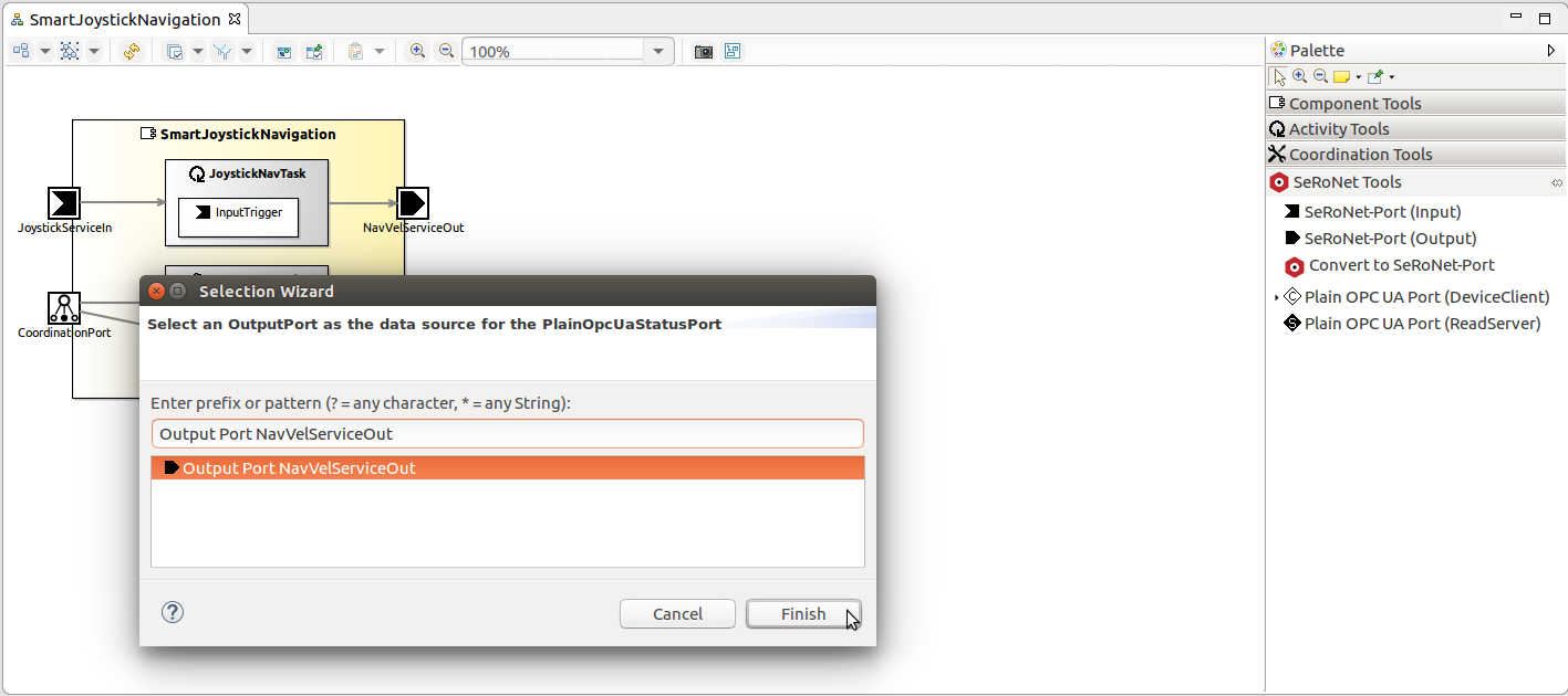 You should now see a new output port “uaNavVelServiceOut” added to the component with a link to the associated output port “NavVelServiceOut” (data source).
 By default, the port number “4840” is utilized for the plain OPC UA Read Server. This, however, can be customized to another value as shown in the screenshow shown below.

Updating the system component
As we have added the port to the component by now. We will update the system accordingly to make use of the newly added port.
In the system project, locate the component architecture diagram for the system “SystemJoystickDemo”. Find and enable SeRoNet tools palette.
 Drag and drop the “Plain OPC UA ReadServer Instance” item from the SeRoNet tools palette onto the component “SmartJoystickNavigation”. This will instantiate and make visible the OPC UA port of the component.

 Select the appropriate ReadServer “uaNavVelServiceOut” and click on the “Finish” button.
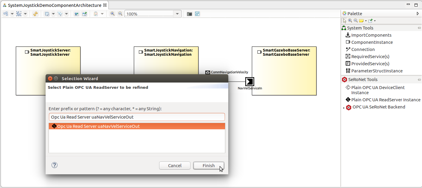 You should now see a new OPC UA ReadServer Instance “uaNavVelServiceOut” added to the component “SmartJoystickNavigation” with a link to the associated output port “NavVelServiceOut” (data source).
 The system “SystemJoystickDemo” is now ready for deployment.

Compiling and Deploying the system project
In this section, we demonstrate how a system is deployed to and executed in a target environment. The general steps are the same as in the dedicated deployment tutorial Develop Your First System by Composing Software Components. The only addition is that we have to launch the OPC UA Client to examine the Read Server.
To compile all components used in the system, you can right-click on the system project, expand the submenu SmartMDSD, and select the CMake command followed by the make all command. After that, you can deploy a system by right-clicking on the system project, expanding the submenu SmartMDSD, and selecting the Deploy command.
The deployment command will copy all the precompiled binaries and libraries, as well as all the required configuration files and start-up scripts to the designated remote location, which in our case is the folder “/tmp” at localhost. Please note that the deployment command uses SSH copy and thus may require to enter the password in case you do not have your ssh key installed.
After the deployment action finishes, a popup dialog will appear asking whether the deployed system should also be started. Confirming to do so by clicking on “yes” will open a new console window:
Running the scenario
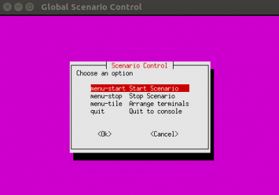
We will now start the composed system by triggering the “Start Scenario” menu option within the console menu. This will execute a naming service, the three components of our system, and the Gazebo simulation environment.
 In addition to the components of the system, also a Gazebo-based simulation environment is automatically started. Moreover, Gazebo should automatically load an office envoronment and initialize a PAL Tiago Robot.
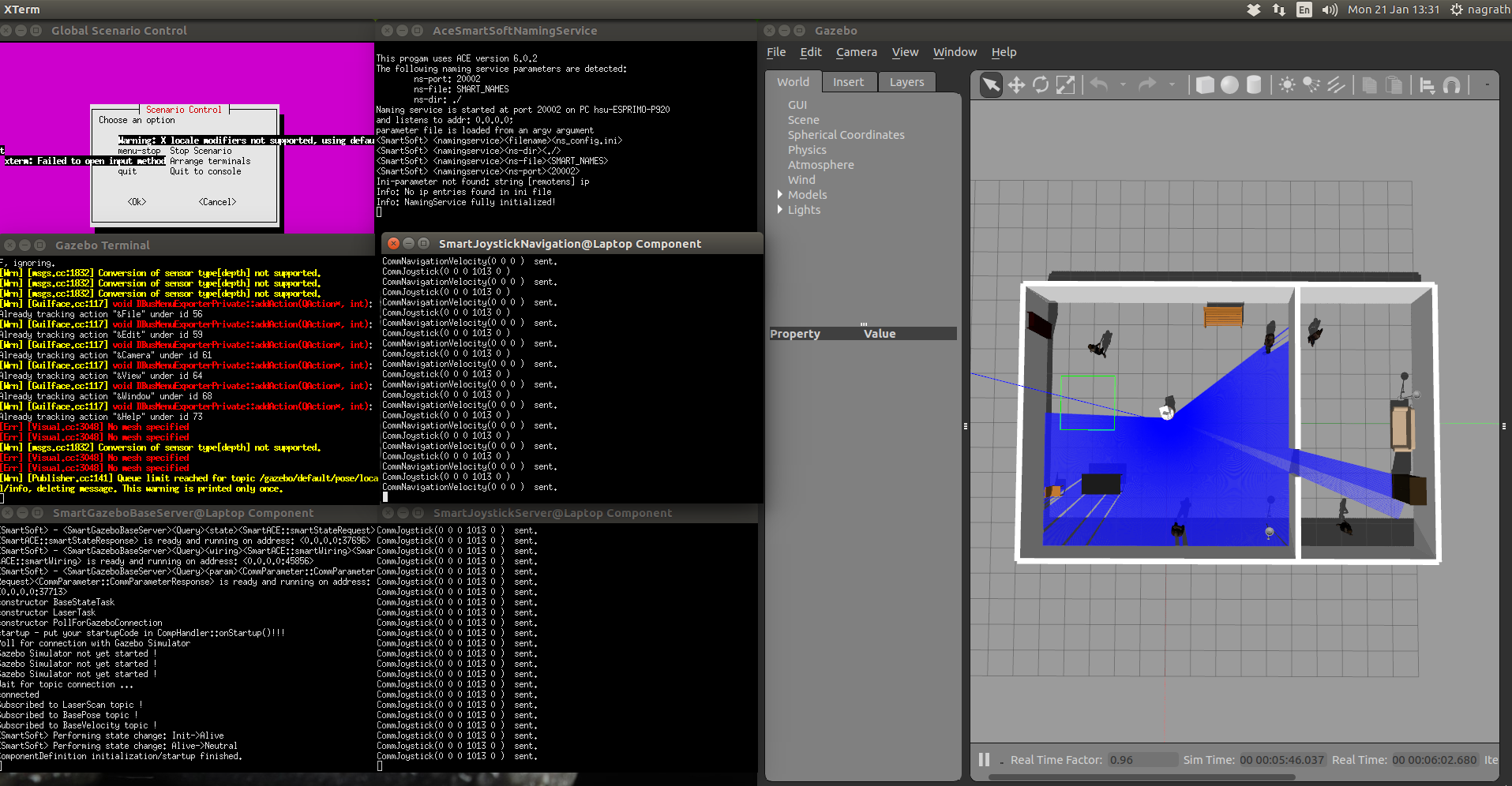
Connecting to the Read Server using a generic OPC UA Client
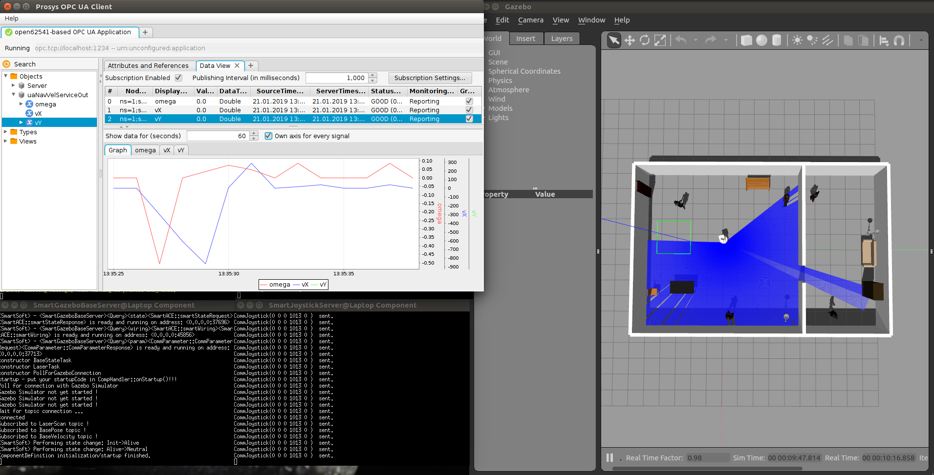
We can now use the plain OPC UA read server just as it were a traditional OPC UA server, e.g. using your favorite OPC UA stack. As an example, we use the Prosys OPC UA Client.
Connect to the Read Server using the IP address of the machine where the scenario is running followed by the port number specified in the properties of the component “ComponentJoystickServer”. In our example the address is:
opc.tcp://localhost:1234
Add variable nodes to the monitor window to observe and/or plot their values.

Running the scenario with simultaneous updates on OPC UA Client
You can now move the robot around using the joystick. The updates can be seen on the monitor window of Prosys OPC UA Client.
Stopping the scenario
Further Information
- Open62541 library (use specific installation instructions


