Table of Contents
Developing Software Components for the Raspberry Pi using GPIO Pins
This tutorial describes how to develop software components using the SmartMDSD Toolchain. We use the WiringPi library to access the GPIO pins.
Basic Information
| Level | Experienced |
|---|---|
| Role | Component Supplier |
| Assumptions | Knowing How to create Components using SmartMDSD Toolchain: Completed tutorial Develop Your First Software Component, basic knowledge of RasperryPi |
| System Requirements | Successfully installed the SmartSoft environment on Raspberry Pi and the SmartMDSD Toolchain on a PC 3 LEDs with transistors, wires, and a breadboard |
| You will learn | How to create a basic component How to build and deploy a single component system on Raspberry Pi How to add external libraries on a Pi How to use the WiringPi library |
Introduction
This tutorial will develop a simple Raspberry Pi powered Traffic Light / Stack Light. The tutorial describes how to develop components using SmartMDSD Toolchain, build and run them manually on a Raspberry Pi, how to add external libraries manually, shows hardware set up of LEDs on a Raspberry Pi.
In this tutorial, WiringPi library is used to access GPIO pins on Raspberry Pi.
By the end of this Tutorial, you will have developed:
- A component that provides a traffic light service: it accesses GPIO pins and turns on and off traffic lights
- A component that uses the traffic light service and commands several light patterns.
You can find examples of these commponents in the Models and Components Directory. In the next tutorial, both components will be composed to a system: Composing a System for the Raspberry Pi
The tutorial is structured as follows:
- Section 1: Creating component for Switching LEDs on a Raspberry Pi
- Create a Basic Component on a PC using SmartMDSD Toolchain, that will be uploaded to Raspberry Pi.
- Learn to build and run a Component manually on a Raspberry Pi.
- Set up LEDs on a breadboard and connect them with Raspberry Pi GPIO pins.
- Add external library to your Component and include it in CMakeLists.txt
- Section 2: Creating Components for a System
- Create a Domain Model including a communication object for communication
- Create a Component for the Raspberry Pi to provide a traffic light service
- Create a Component for the PC to use the traffic light service
Section 1. Creating, Building and Running Component on Raspberry Pi
In this Section we will create a basic component, that will blink LEDs on a Raspberry Pi. You will get all necessary information, including hardware setup, building, testing and manually deploying Component.
Section 1.1. Create a Basic Component on a PC and upload it to Raspberry Pi
Create a basic component that will have a loop for switching lights. We will create the component on a development computer and later transfer it to the raspberry pi for execution.
- Create Component and call it ComponentRaspberryLeds in ~/SOFTWARE/smartsoft-ace-mdsd-v3/repos/ComponentRepository/ComponentRaspberryLeds
- Drag Activity from
Palette ⇒ Activity Tools ⇒ Activityand Drop it inside your Component. Rename Activity1 to SwitchLEDs. Left click on Activity1, then Properties ⇒ General ⇒ Name. Type SwitchLEDs.
- Drag Periodic Timer from
Palette ⇒ Activity Tools ⇒ Periodic Timerand Drop it inside of your activity (SwitchLEDs in this case)
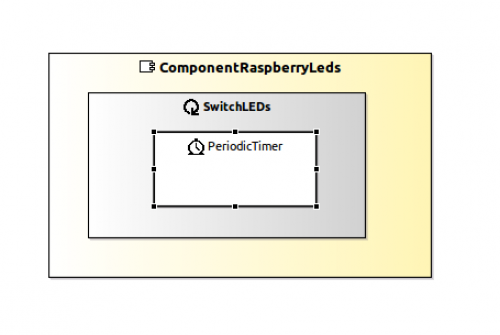
If you`ve done everything correctly, your component model should look like this:
Now let`s add some print statements for testing purposes. Open SwitchLEDs.cc in Project Explorer ⇒ ComponentRaspberryLeds ⇒ smartsoft ⇒ SwitchLEDs.cc
Inside SwitchLEDs.cc find int SwitchLEDs::on_execute() function. Add some print statements to it for the testing purposes:
int SwitchLEDs::on_execute()
{
    // this method is called from an outside loop,
    // hence, NEVER use an infinite loop (like "while(1)") here inside!!!
    // also do not use blocking calls which do not result from smartsoft kernel

    // to get the incoming data, use this methods:
    Smart::StatusCode status;

    std::cout << "Hello from SwitchLEDs " << std::endl;

    std::cout << "Red" << std::endl;
    std::cout << "Yellow" << std::endl;
    std::cout << "Green" << std::endl;
    std::cout << "Yellow" << std::endl;

    // it is possible to return != 0 (e.g. when the task detects errors), then the outer loop breaks and the task stops
    return 0;
}
For testing purposes CMake and Build your ComponentRaspberryLeds with right mouse click on ComponentRaspberryLeds ⇒ build.
Once it`s done you are ready to load your Component on the Raspberry Pi. If you have problems with this part of the Tutorial please review Develop Your First Software Component.
Uploading Component on a Raspberry Pi
Now you have to copy your component to the Pi. We suggest to use version control such as git (e.g. via GitHub) and later checking out/cloning it in a chosen directory on a Raspberry Pi with the following commands. We'll assume your repository url is at Github.
git clone https://github.com/yourComponent.git
Please check if content of components smartsoft/src-gen folder has been added. If not you can do it with:
git add -f <pathToComponent>/smartsoft/src-gen/*
To learn more about how to version control artifacts of the SmartMDSD Toolchain, see HowTo's and FAQ.
Section 1.2 Manually building Component on a Raspberry Pi
Using a terminal, navigate to the location of your component:
cd <component folder>/smartsoft
It is good practice to have all files included in the repository that are necessary for compilation. You do not need the build/ directory in version control. Delete it in case you checked it in. We will now compile the project on the PI. That is necessary since the computer architecture of the development PC and of the PI are different. Cross-compiling would solve this, but is a feature that is planned for the future. To build the component, use the following commands in the terminal:
mkdir build            #in case you never built the component before
cd build
cmake ..
make
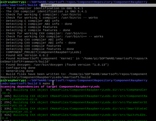
It will look like this:
Once your component is build you can test it with the following commands (see Installation of the SmartSoft World):
cd $SMART_ROOT_ACE                # leads to ~/SOFTWARE/smartsoft
./startSmartSoftNamingService     # there are also stop and show commands for NamingService
                                  # 'Enter' should be pressed after initialisation of NamingService
bin/ComponentRaspberryLeds        # Run the Component
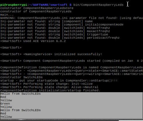
If the test of your component was successful your output should look like this:
If you have problems with this part of the tutorial, review testing_smartsoft_on_a_raspberry_pi.
Section 1.3. Hardware Setup on Rapsberry Pi
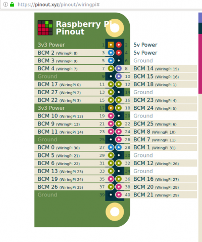
On https://pinout.xyz/pinout/wiringpi# you can see the layout of GPIO pins.
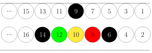
In this example we will be using the WiringPi library, GPIO ports WiringPi 15,16,1 which are equivalent to BCM 14, 15, 18.
- Pin 8 ⇒ BCM 14 ⇒ WiringPi 15 ⇒ Red
- Pin 10 ⇒ BCM 15 ⇒ WiringPi 16 ⇒ Yellow
- Pin 12 ⇒ BCM 18 ⇒ WiringPi 1 ⇒ Green
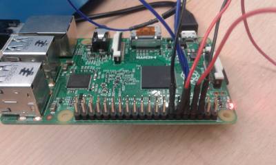
If you turn the Raspberry Pi with GPIO pins facing you, as shown on the picture, the pins numbering will be going from Right to Left in ascending order. The pins closer to you will be even. The pins further from you will be odd.
The picture above represents GPIO pins on Raspberry Pi in this hardware setup. Black circles represent Ground, Red Circle represents Red LED power source that when using WiringPi library is under number 15, Yellow Circle represents Yellow LED(pin 10, WiringPi 16) power source, Green Circle represents Green LED(pin 12, WiringPi 1) power source. The White circles represent pins that were not used in our hardware setup.
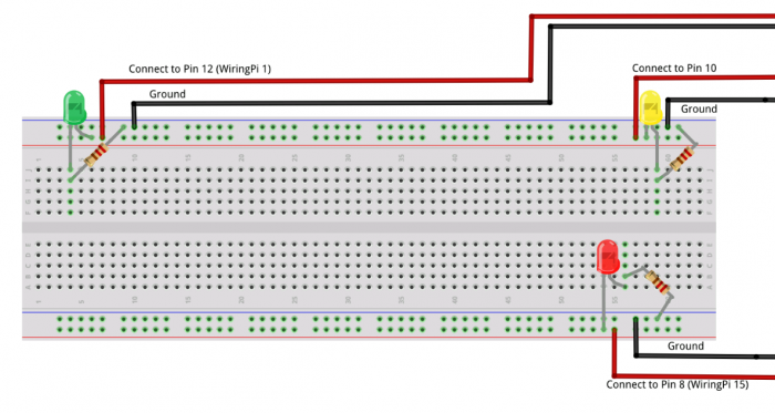
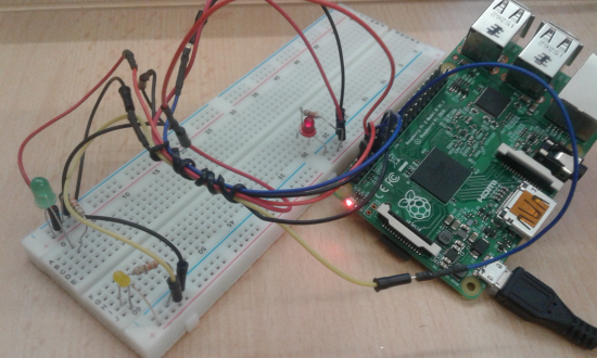
And here`s the full picture of the Hardware Setup. Remember to make sure that you are using appropriate resistors for your LEDs and that they are connected with the correct LED pin (short leg minus; long leg plus).
To test your hardware setup you can execute in terminal following commands. Remember, these commands are using BCM layout, not the WiringPi, so don`t be confused with different pin numbering.
gpio -g mode 14 out 		#sets BCM GPIO pin 14 in the output mode (Red)
gpio -g write 14 1 		#if you did all correctly you should see Red LED ON
gpio -g write 14 0 		#turns OFF Red LED
gpio -g mode 15 out 		#sets BCM GPIO pin 15 in the output mode (Yellow)
gpio -g write 15 1		#Yellow LED ON
gpio -g write 15 0		#Yellow LED OFF
gpio -g mode 18 out
gpio -g write 18 1		#Green LED ON
gpio -g write 18 0		#Green LED OFF
Extending your Components Code with external Library on a Pi
We have confirmed that the LEDs work with the Raspberry Pi. We will now setup the software component to turn on and off the LEDs.
First, let`s download the WiringPi library by executing the following command in terminal:
sudo pip install wiringpi2
Now we have to add the WiringPi library. Open the SwitchLEDs.cc file, located in ComponentRaspberryLeds/smartsoft/src folder and include wiringPi library by adding:
Inside the int SwitchLEDs::on_entry() function declare the wiringPi setup and set the necessary GPIO pins to output mode:
Extend int SwitchLEDs::on_execute() to turn ON and OFF LEDs:
Section 1.4 Adding external library to CMakeLists
The WiringPi library is now included in source code. We have to make the compiler aware of it in Cmake.
Go to <your component>/smartsoft.
Open CMakeLists.txt.
Somewhere between line 60 and 70, you will see the following 2 lines:
# link your external libraries here (if there are any)
#TARGET_LINK_LIBRARIES(${PROJECT_NAME} <your-libs>)
Uncomment the second line and instead of “<your-libs>“ insert the wiringPi library:
# link your external libraries here (if there are any)
TARGET_LINK_LIBRARIES(${PROJECT_NAME} wiringPi)
Then rebuild your code by entering <component>/smartsoft/build directory via terminal and executing the following commands:
cmake ..
make
Now you are ready to start the NamingService and your Components in ~/SOFTWARE/smartsoft directory.
cd $SMART_ROOT_ACE
./startSmartSoftNaming #press :'Enter', after the NamingService has started

bin/ComponentMostBasicLight
If all was done correctly, you should see the blinking LEDs.
Section 2 Creating Components for a System
So far we have shown how to use GPIO pins of the Raspberry Pi with the SmartMDSD Toolchain. In this section of the tutorial, we will create two components that will be used in Composing a System for the Raspberry Pi:
- ComponentTrafficLight, that will be located on a Raspberry Pi and will turn on and off LEDs
- ComponentTrafficLightTest, located on a PC, will tell the ComponentTrafficLight which LEDs to turn on and off
- Further, we will model a communication object. It is the data structure that is being communicated between both components to transfer the necessary information.
First, we need to define CommTrafficLight signals in a Domain Model.
Section 2.1. Communication Domain Model
We will now create a domain model. This is in detail described in Develop Your First Domain Model.
1. Create a new Domain model and call it DomainHMI. New ⇒ Domain-Models Project(Tier2)…
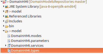
2. Open DomainHMI ⇒ Model ⇒ DomainHMI.services and insert the following code:
ServiceDefRepository DomainHMI version 1.0 {

    // Service definition to command a traffic light
    JoiningServiceDefinition TrafficLightService {
        SendPattern <DataType=DomainHMI.CommTrafficLight>
    }

}
3. Define a Communication Object CommTrafficLight in DomainHMI.types file:
CommObjectsRepository DomainHMI version 1.0 {

   /**
    * The communication object to set the state of a traffic light.
    * Each boolean variable represents the red/green/yellow light of the traffic light.
    */
   CommObject CommTrafficLight {
	// variable to hold status of the red light. true=on, false=off
        red: Boolean = false

        // variable to hold status of the green light. true=on, false=off
        green: Boolean = false

        // variable to hold status of the yellow light. true=on, false=off
        yellow: Boolean = false
   }

}
The code for DomainHMI was given with documentation. If you are interested in how to document and annotate your model with the Digital Datatsheet, you can read about it here: https://wiki.servicerobotik-ulm.de/how-tos:documentation-datasheet:start
4. Make sure you have DomainHMI model on both Raspberry PI and PC in ~/SOFTWARE/smartsoft/repos/DomainModelsRepositories
5. Build your DomainHMI project on both systems.
On PC, use the SmartMDSD Toolchain:
SmartSoft Build Tools ⇒ CMake and then SmartSoft Build Tools ⇒ build all
On Raspberry, use the command line:
 cd $SMART_ROOT_ACE/repos/DomainModelsRepositories/DomainHMI/smartsoft
 mkdir build; cd build
 cmake..
 make
If you already have a build folder in your DomainHMI folder on Raspberry Pi, then clean it and rebuild the project:
 cd $SMART_ROOT_ACE/repos/DomainModelsRepositories/DomainHMI/smartsoft/build
 rm -rf *
 cmake..
 make
Section 2.2. Traffic Light Component
Now lets create the ComponentTrafficLight, the component that provides a service to turn on and off LEDs of a traffic light. If you encounter problems in this part of the tutorial, review Develop Your First Software Component
1. Create a new Component and call it ComponentTrafficLight.
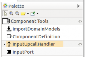
2. Import DomainHMI model by drag and dropping: Palette ⇒ ComponentTools ⇒ ImportDomainModels
3. Assign an Input Port by drag and dropping it on the Component:
Palette ⇒ ComponentTools ⇒ InputPort
4. Assign InputHandler Port by drag and dropping it on the Component (Usually located under InputPort. If you don`t see it, press on the small triangle to the right side of it):
Palette ⇒ ComponentTools ⇒ InputUpcallHandler
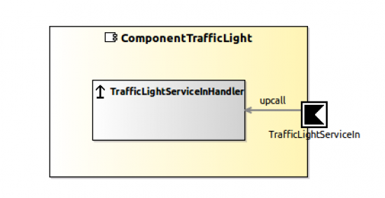
Now your component should look as follows:
5. Edit ComponentTrafficLight ⇒ smartsoft ⇒ src ⇒ TrafficLightServiceInHandler.cc
Now in the CompHandler.cc you need to set the GPIO Pin Modes to OUTPUT and write the clean up code. This is similar to what we did in int SwitchLEDs::on_entry() in our previous example extending_your_components_code_with_external_library_on_a_pi, but it is a better practice to make the StartUp and CleanUp tasks in CompHandler.cc.
6.Inside ComponentTrafficLight ⇒ smartsoft ⇒ src ⇒ CompHandler.cc modify the void CompHandler::onStartup() routine by setting the Pin Modes to OUTPUT. And write the clean up code in void CompHandler::onShutdown(), as shown below:
7. Upload your Component folder on Raspberry Pi.
8. On Raspberry Pi, add the wiringPi.h library to CMakeLists.txt as shown in section_14_adding_external_library_to_cmakelists.
9. CMake and make all operation on Raspberry Pi as you did with your previous component and you`re done with the Provider Component of your system.
Section 2.3. Test Component
We will now create a simple test component that uses the service provided by ComponentTrafficLight. It will command several blinking patterns.
1. Create a new Component and call it ComponentTrafficLightTest.
2. Import DomainHMI model by drag and dropping Palette ⇒ ComponentTools ⇒ ImportDomainModels
3. Assign an Activity by drag and dropping Palette ⇒ Activity Tools ⇒ Activity on the Component. Call it GenerateOut
4. Add a PeriodicTimer by drag and dropping Palette ⇒ Activity Tools ⇒ PeriodicTimer inside the GenerateOut Activity.
5. Add OutputPort by drag and dropping Palette ⇒ ComponentTools ⇒ OutputPort inside the Component.
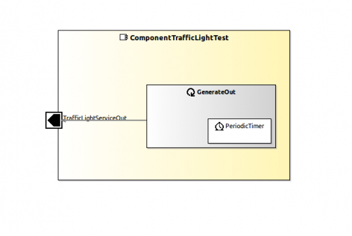
Now your Component should look like this:
6. Go to ComponentTrafficLightTest ⇒ smartsoft ⇒ src ⇒ GenerateOut.cc and modify content of the file, so it looks like this:
Cmake and make all using SmartSoftBuild Tools. Now you`re done with your second Component and ready to start Composing a System for the Raspberry Pi.
What do do next?
Now you can proceed with Composing a System for the Raspberry Pi tutorial, where you will build a System on a Raspberry Pi with Components you just created.

